
F 150 4WD V8-5.4L Flex Fuel (2008)
Removal and Installation
WARNING: Do not use any fluid other than clean brake fluid meeting manufacturer's specification. Additionally, do not use brake fluid that
has been previously drained. Following these instructions will help prevent system contamination, brake component damage and the risk of
serious personal injury.
WARNING: Carefully read cautionary information on product label. For EMERGENCY MEDICAL INFORMATION seek medical advice.
In the USA or Canada on Ford/Motorcraft products call: 1-800-959-3673. For additional information, consult the product Material Safety
Data Sheet (MSDS) if available. Failure to follow these instructions may result in serious personal injury.
CAUTION: Brake fluid is harmful to painted and plastic surfaces. If brake fluid is spilled onto a painted or plastic surface, immediately wash
it with water.
CAUTION: Electronic modules are sensitive to electrical charges. The anti-lock brake system (ABS) module can be damaged if exposed to
these charges.
CAUTION: When installing a new anti-lock brake system (ABS) module or hydraulic control unit (HCU), do not use the pump motor
harness as a carrying handle. Failure to follow these instructions may result in damage to the HCU assembly.
CAUTION: When disconnecting the brake tubes, do not allow brake fluid to drip onto the anti-lock brake system (ABS) module or
premature failure may occur.
CAUTION: Do not allow brake fluid to drip into the anti-lock brake system (ABS) module electrical connector cavity or premature failure
may occur.
All vehicles
1. Disconnect the battery ground cable. For additional information, refer to Battery.
Vehicles equipped with 5.4L engine
2. Remove the air cleaner intake pipe. For additional information, refer to Fuel Delivery and Air Induction.
Vehicles equipped with 4.6L and 4.2L engine
3. Remove the air cleaner assembly. For additional information, refer to Fuel Delivery and Air Induction.
All vehicles
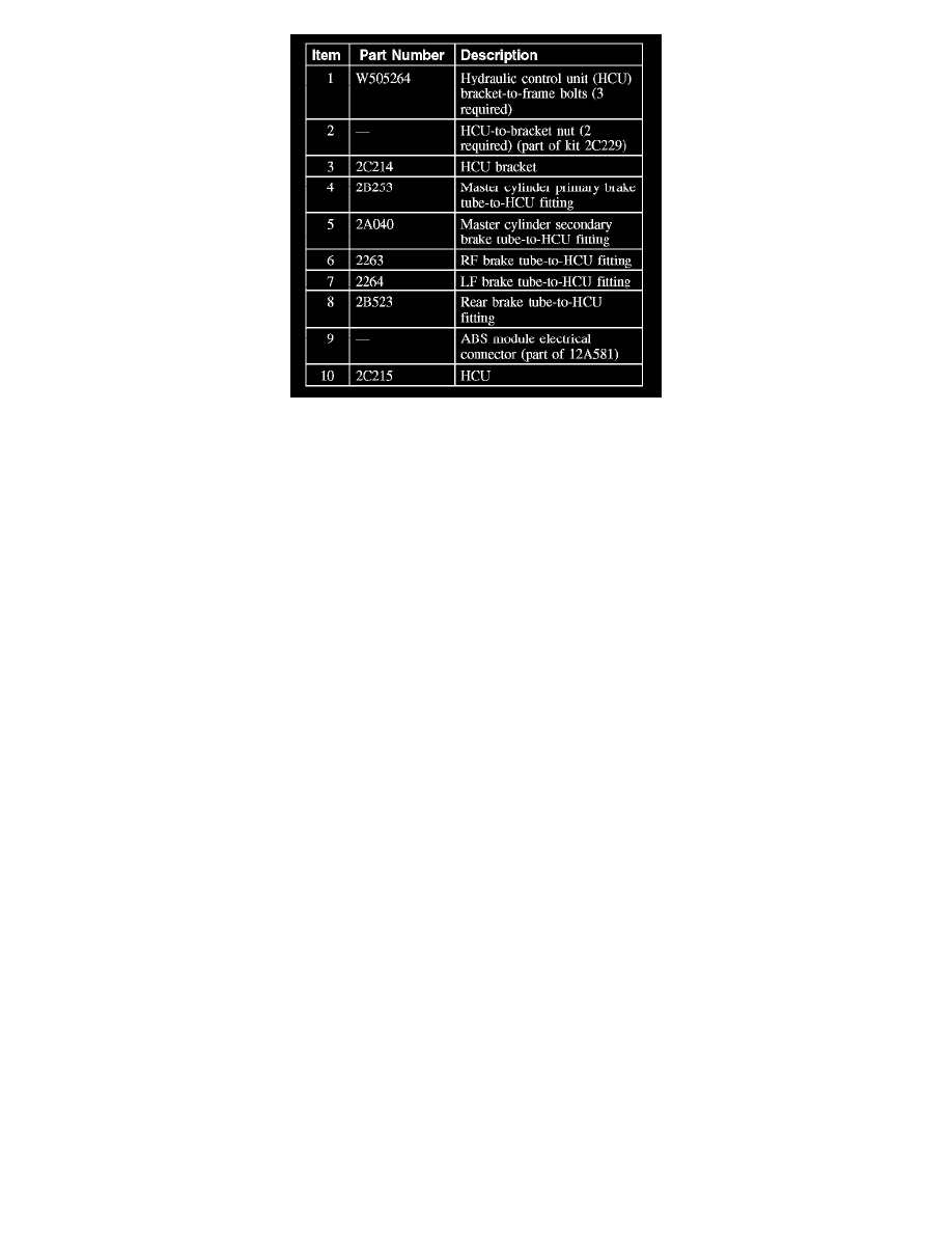
4. NOTE: The brake tubes must be installed in the same location as removed.
Remove the 5 brake tube-to-hydraulic control unit (HCU) fittings.
^
To install, tighten to 22 Nm (16 lb-ft).
5. Remove the 2 HCU-to-bracket nuts and the HCU.
^
To install, tighten to 8 Nm (71 lb-in).
6. Remove the ABS module.
7. NOTE: The HCU bracket does not have to be removed in order to complete this procedure.