
F 150 4WD V8-5.4L Flex Fuel (2008)
-
ISO 9141
-
UBP
ISO 9141 Communications Network
The ISO 9141 communications network is a single wire network. The ISO 9141 communications network does not permit intermodule
communication. When the scan tool communicates to modules on the ISO 9141 communication network, the scan tool must request all information;
the modules cannot initiate communications. The ISO 9141 network operates at a maximum data transfer speed of 10.4 Kbps.
The following modules are on the ISO 9141 network:
-
Parking aid module (PAM) (if equipped)
-
Restraints control module (RCM)
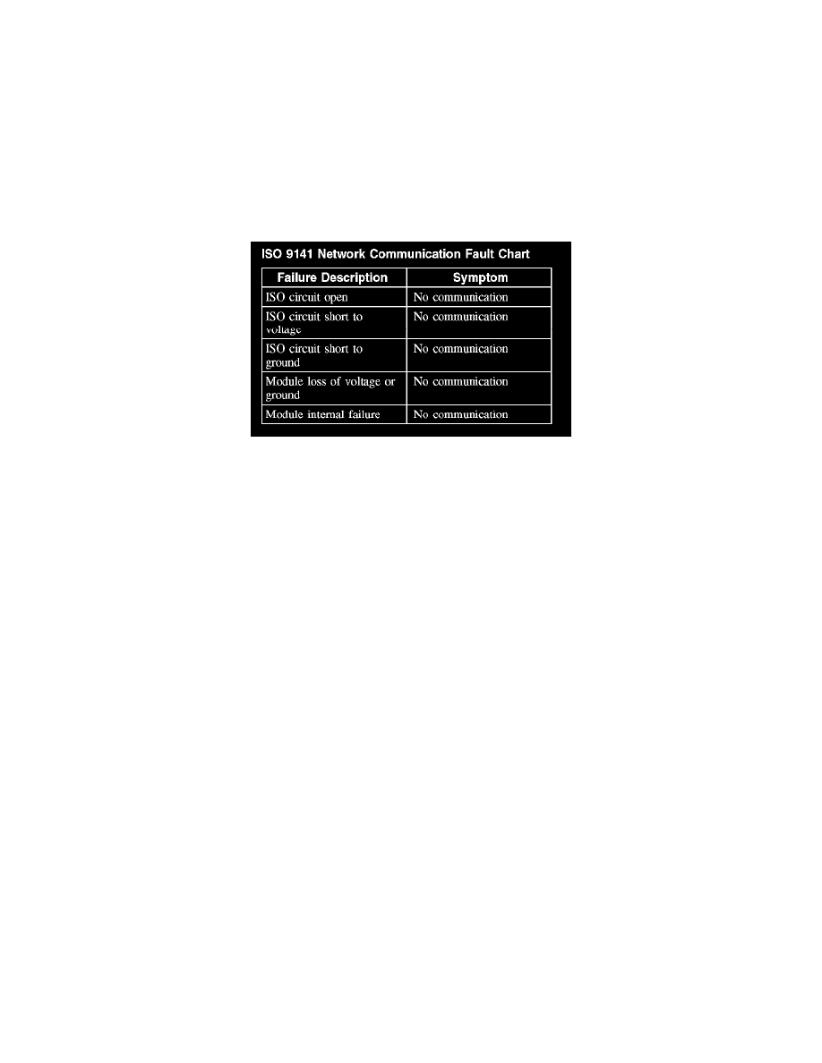
The following fault chart describes the specific ISO 9141 network failures and their resulting symptom:
ISO 9141 Network Communication Fault Chart
HS-CAN
The HS-CAN uses an unshielded twisted pair cable of data (+) and data (-) circuits. The data (+) and the data (-) circuits are each regulated to
approximately 2.5 volts during neutral or rested network traffic. As bus messages are sent on the data (+) circuit, voltage is increased by
approximately 1.0 volt. Inversely, the data (-) circuit is reduced by approximately 1.0 volt when a bus message is sent. Multiple bus messages can be
sent over the CAN circuits allowing network modules to communicate with each other.
The CAN bus (+) and bus (-) circuits must always be terminated. The network termination of the CAN bus takes place inside the 2 termination
modules, the PCM and the instrument cluster (IC), by resistors rated at 120 ohms, located across the (+) and (-) circuits. The resistors are wired in
parallel to the network bus circuits for a total operating resistance of 60 ohms on a good network.
The HS-CAN operates at a maximum data transfer speed of 500 Kbps and remains operational at a degraded level when certain circuit faults are
present. The HS-CAN bus may remain operational with only one termination resistor present.
The following modules are on the HS-CAN:
-
ABS module
-
IC
-
PCM with integrated 4X4 control module
The following fault chart describes the specific HS-CAN failures and their resulting symptom: