
F 150 4WD V8-5.4L Flex Fuel (2008)
5. NOTE: The manual control lever must be in the NEUTRAL position.
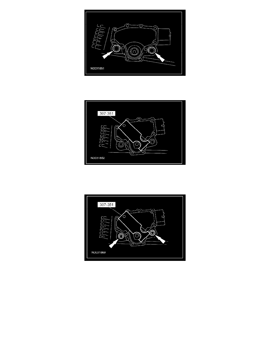
Using the special tool, align the digital TR sensor slots. The tool is designed to fit snug.
6. CAUTION: Tightening one bolt before tightening the other may cause the sensor to bind or become damaged.
Using the special tool, align the digital TR sensor and tighten the bolts in an alternating sequence.
^
Tighten to 9 Nm (80 lb-in).
7. Install the manual control lever.
1
Position the manual control lever.
2
Install a new manual control lever shaft outer nut.
^
Tighten to 33 Nm (24 lb-ft).