
F 150 4WD V8-5.4L Flex Fuel (2008)
1. Depower the SRS.
2. Make sure the road wheels are in the straight-ahead position.
3. Remove the driver air bag module.
4. Remove the steering wheel.
5. Remove the screw and lower steering column shroud.
6. Remove the 2 upper steering column shroud screws and upper steering column shroud.
7. If installing the same clockspring, apply 2 strips of masking tape across the clockspring to prevent accidental rotation when the clockspring is
removed.
8. Remove the multi-function switch screw.
9. Remove the screw and the multi-function switch.
-
While releasing the retaining tab at the top of the multi-function switch, slide the multi-function switch up and aside.
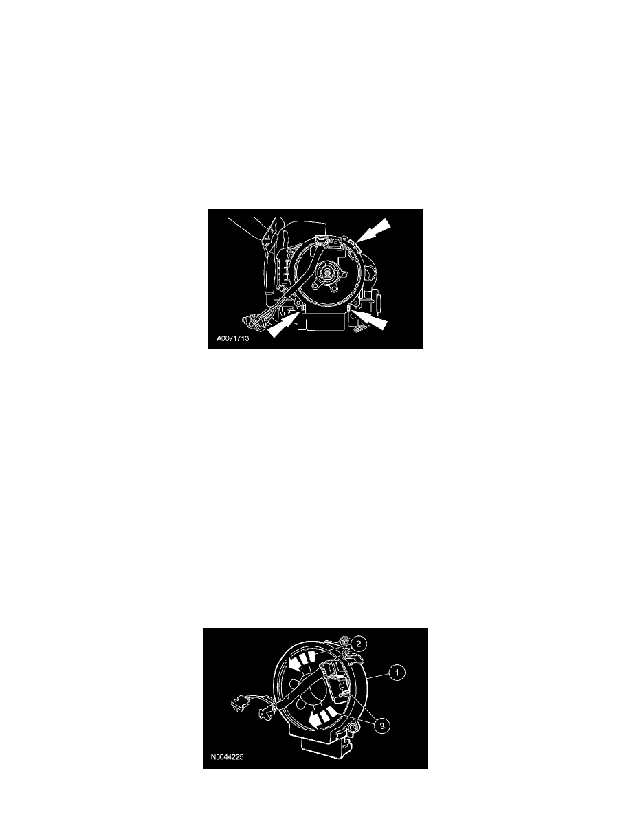
10. Disconnect the clockspring electrical connectors.
11. Release the 3 clips and remove the clockspring.
12. Inspect the clockspring mounting bracket for damage and install a new mounting bracket as necessary.
-
To install, tighten to 6 Nm (53 lb-in).
Installation
1. WARNING: If the clockspring is not correctly centralized, it may fail prematurely. If in doubt, repeat the centralizing procedure.
Failure to follow these instructions may increase the risk of serious personal injury or death in a crash.
CAUTION: Make sure the road wheels are in the straight-ahead position or damage to the clockspring can occur.
If the vehicle's clockspring has rotated out of center, follow these steps to center the clockspring.
1
Hold the clockspring outer housing stationary.
2
CAUTION: Overturning will destroy the clockspring. The internal ribbon wire acts as the stop and can be broken from its internal
connection.
While turning the rotor counterclockwise, carefully feel for the ribbon wire to run out of length and for a slight resistance. Stop turning at this
point.
3
Turn the clockspring clockwise approximately 3 turns. This is the center point of the clockspring.
-
Do not allow the rotor to turn from this position. To prevent accidental rotation until the clockspring is installed, 2 pieces of tape may be
applied to the clockspring.