
F 150 4WD V8-5.4L Flex Fuel (2008)
CAUTION:
-
While positioning the seat cushion pan and occupant classification sensor (OCS) assembly, be careful not to damage any of the
components. Failure to do so can result in component failure.
-
To prevent system failure, it is necessary to carry out the occupant classification sensor (OCS) system reset when a front passenger
seat cushion is disassembled, a new trim cover installed or an OCS system service kit is installed. A scan tool is used to carry out the
OCS system reset command.
-
Do not install a new heater mat on a front passenger seat cushion. If a new cushion heater mat is needed on the front passenger seat,
an occupant classification sensor (OCS) service kit equipped with a heater mat must be installed. Failure to follow this instruction
may result in incorrect operation of the OCS system.
NOTE:
-
Occupant classification sensor (OCS) system components (seat wiring harness, seat cushion frame, seat cushion foam pad, bladder with
pressure sensor and occupant classification system module [OCSM]) are calibrated to each other and are serviced as an assembly. The OCS
system components are not to be installed separately. If a new OCS system, OCS system component or seat cushion foam pad are needed, an
OCS system service kit (seat cushion frame, seat cushion foam pad, bladder with pressure sensor, seat wiring harness and OCSM) must be
installed as an assembly.
-
To identify between a production OCS system and an OCS service kit, inspect the OCSM electrical connector.
A production OCS system allows the disconnect of the electrical connector from the OCSM.
An OCS system service kit has the OCSM electrical connector glued to the module. It cannot and should not be disconnected or altered.
-
The air bag warning indicator illuminates when the restraints control module (RCM) fuse is removed and the ignition switch is ON. This is
normal operation and does not indicate a supplemental restraint system (SRS) fault.
-
The SRS must be fully operational and free of faults before releasing the vehicle to the customer.
-
Repair is made by installing a new part only. If the new part does not correct the condition, install the original part and carry out the diagnostic
procedure again.
1. Remove the passenger seat.
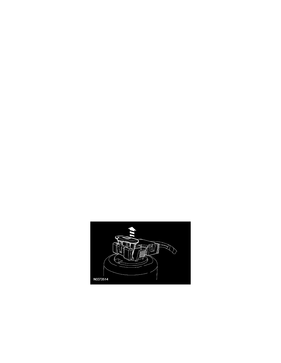
2. CAUTION: To prevent component damage and avoid setting DTCs, the following precautions must be taken when disconnecting the
safety belt buckle pretensioner.
-
The position assurance locking wedge must be in the released position when inserting or removing the electrical connector from the
safety belt buckle and pretensioner.
-
Do not install the electrical connector by pushing on the position assurance locking wedge.
-
Make sure the electrical connector and position assurance locking wedge are fully seated after connecting to the safety belt buckle and
pretensioner.
Release the locking wedge on the safety belt buckle and pretensioner electrical connector.
3. Disconnect the safety belt buckle switch and pretensioner electrical connectors.
4. NOTE: Vehicles without seat integrated restraints (SIR) will have the belt tension sensor (BTS) connector at the B-pillar and will not have to be
disconnected for this procedure.
Disconnect the BTS electrical connector and route out the wire harness (vehicles with SIR only).
5. Remove the seat cushion nuts.
6. If equipped with manual lumbar, release the J-clip and route out the manual lumbar cable.