
F 150 4WD Pickup V8-302 5.0L (1986)
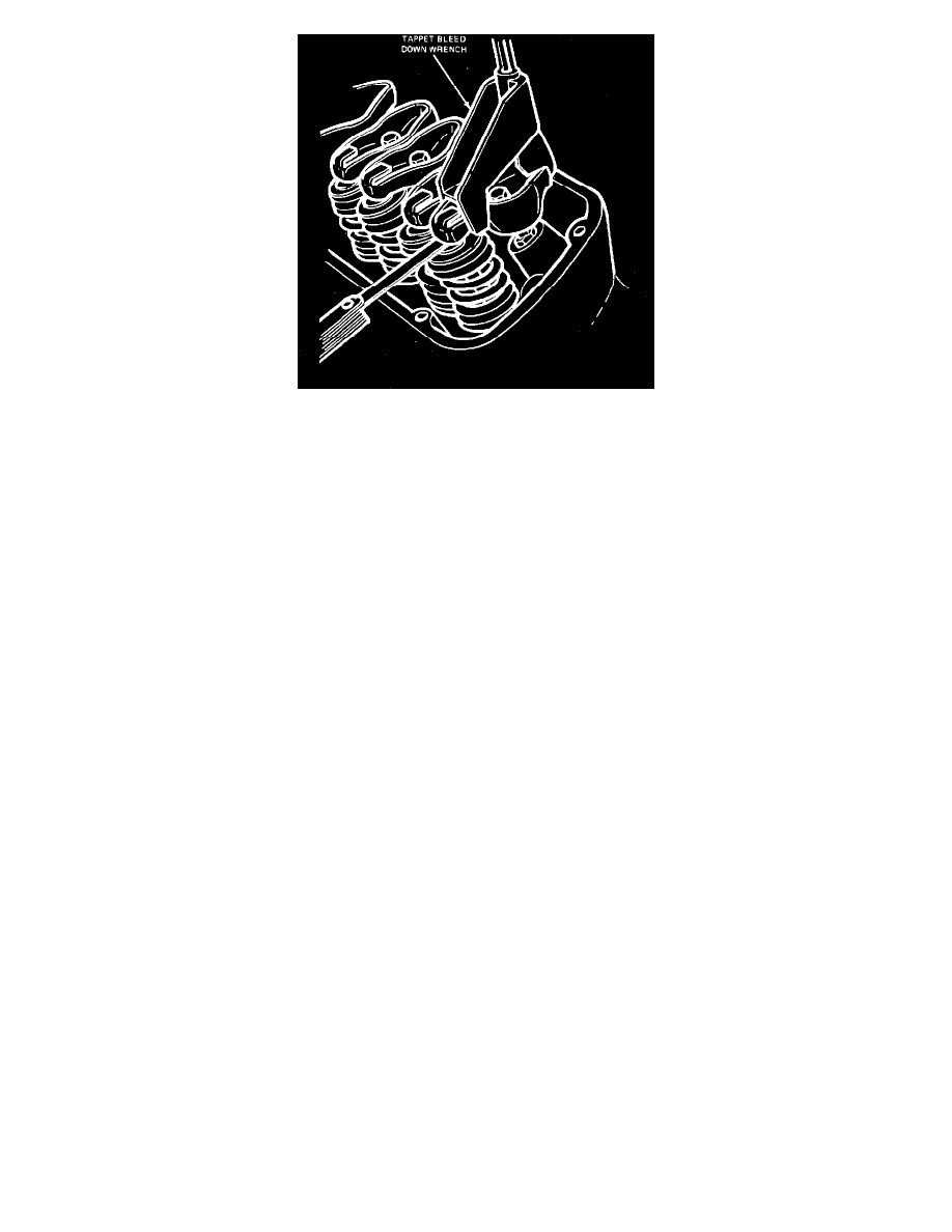
Fig. 3 Checking collapsed tappet clearance
Valves, Adjust
To provide a means to compensate for dimensional changes in the valve train and provide for valve adjustment, .060 inch shorter or longer pushrods
are available. If the valve clearance is less than the minimum, the .060 inch shorter pushrod should be used. If the clearance is more than the maximum,
the longer pushrod should be used. To check the valve clearance, proceed as follows:
1.
Mark crankshaft pulley at three locations, with No. 1 location at TDC timing mark (end of compression stroke), location No. 2 one full turn (360°)
clockwise from TDC and No. 3 location one quarter turn clockwise (90°) from position No. 2, Fig. 2.
2.
Turn crankshaft to number 1 location, then compress valve lifter using tool T71P-6513-A or equivalent, Fig. 3, and check the clearance on the
following valves:
a. On V8-302 and 460 engines, check intake valve Nos. 1 , 7 and 8; exhaust valve Nos. 1, 4 and 5.
b. On V8-351, check intake valve Nos. 1, 4 and No. 8; exhaust valve Nos. 1, 3 and 7.
3.
Turn crankshaft to number 2 location, then compress valve lifter using tool T71P-6513-A or equivalent, Fig. 3, and check the clearance on the
following valves:
a. On V8-301 and 460 engines check intake valve Nos. 4 and 5; exhaust valve Nos. 2 and 6.
b. On V8-351 engines, check intake valve Nos. 3 and 7; exhaust valve Nos. 2 and 6.
4.
Turn crankshaft to number 3 location, then compress valve lifter using tool T71P-6513-A or equivalent and check the clearance on the following
valves:
a. V8-302 and 460 engines check intake valve Nos. 2, 3 and 6; exhaust valve Nos. 3, 7 and 8.
b. On V8-351 engines, check intake valve Nos. 2, 5 and 6; exhaust valve Nos. 4, 5 and 8.
Valve Arrangement
Front to Rear
V8-302 Left Bank.............................................................................................................................................................................................E-I-E-I-E-I-E-I
V8-302 Right Bank...........................................................................................................................................................................................I-E-I-E-I-E-I-E
V8-351 Right Bank...........................................................................................................................................................................................I-E-I-E-I-E-I-E
V8-351 Left Bank.............................................................................................................................................................................................E-I-E-I-E-I-E-I
V8-460 Left Bank.............................................................................................................................................................................................E-I-E-I-E-I-E-I
V8-460 Right Bank...........................................................................................................................................................................................I-E-I-E-I-E-I-E