
F 150 4WD Pickup V8-5.4L CNG VIN M (2001)
Fuel Rail: Adjustments
BI-FUEL MODELS
Special Tool(s)
SPECIAL TOOL(S)
WARNING:
^
CERTAIN STEPS IN THIS PROCEDURE REQUIRE THE VEHICLE TO BE RUNNING, IN GEAR AND THE ENGINE
ACCELERATED. BE SURE THAT THE PARKING BRAKE IS FULLY SET AND THE WHEELS ARE CORRECTLY CHOCKED.
TAKE ALL NECESSARY PRECAUTIONS TO AVOID INJURY AND PROPERTY OR EQUIPMENT DAMAGE.
^
THE ALTERNATIVE FUEL (CNG OR LPG) LINES AND COMPONENTS ARE PRESSURIZED. USE CARE WHEN SERVICING
THE SYSTEM AND TAKE ALL NECESSARY PRECAUTIONS TO AVOID PERSONAL INJURY. ALWAYS FOLLOW ALL
APPLICABLE PROCEDURES CONCERNING FUEL LEAK TESTING AND FUEL SYSTEM INSPECTION.
1. Place the vehicle in an appropriate service bay, set the parking brake, and correctly place wheel chocks both in front of and behind the front
wheels. Connect the exhaust to a vacuum exhaust system and provide adequate ventilation.
2. Select the OFF position of the ignition switch, and the ALT position of the ALT fuel selection switch.
3. Connect the vacuum/pressure tester, tool # 164-R0253 or equivalent, to an appropriate source of intake manifold vacuum.
4. Connect the New Generation STAR (NGS) Tester, tool # 418-F048 or equivalent, to the vehicle diagnostic Data Link Connector (DLC). Turn the
ignition switch to the ON position. Select, monitor, and record Powertrain Control Module (PCM) data PIDs ECT, O2S11, and O2S21.
5. Start and run the engine while monitoring the PCM PID ECT. Allow the engine to warm up until the PCM PID ECT indicates 190 degrees F.
WARNING: THIS STEP REQUIRES THE VEHICLE TO BE RUNNING, IN GEAR AND THE ENGINE ACCELERATED. BE SURE
THAT THE PARKING BRAKE IS FULLY SET AND THE WHEELS ARE CORRECTLY CHOCKED. TAKE ALL NECESSARY
PRECAUTIONS TO AVOID INJURY AND PROPERTY OR EQUIPMENT DAMAGE.
6. Select, monitor, and record the alternative fuel control module (AFCM) PID MAP and vacuum. Place the transmission gear in reverse while
applying the brake pedal then slowly apply pressure to the accelerator pedal. Continue to accelerate until the AFCM PID MAP indicates 7.3 or 7.4
PSI and record the vacuum. This vacuum value point will be used in the remaining procedure steps as the 'tuning point'.
7. Allow the accelerator to return to the idle position and place the transmission gear in the park position.
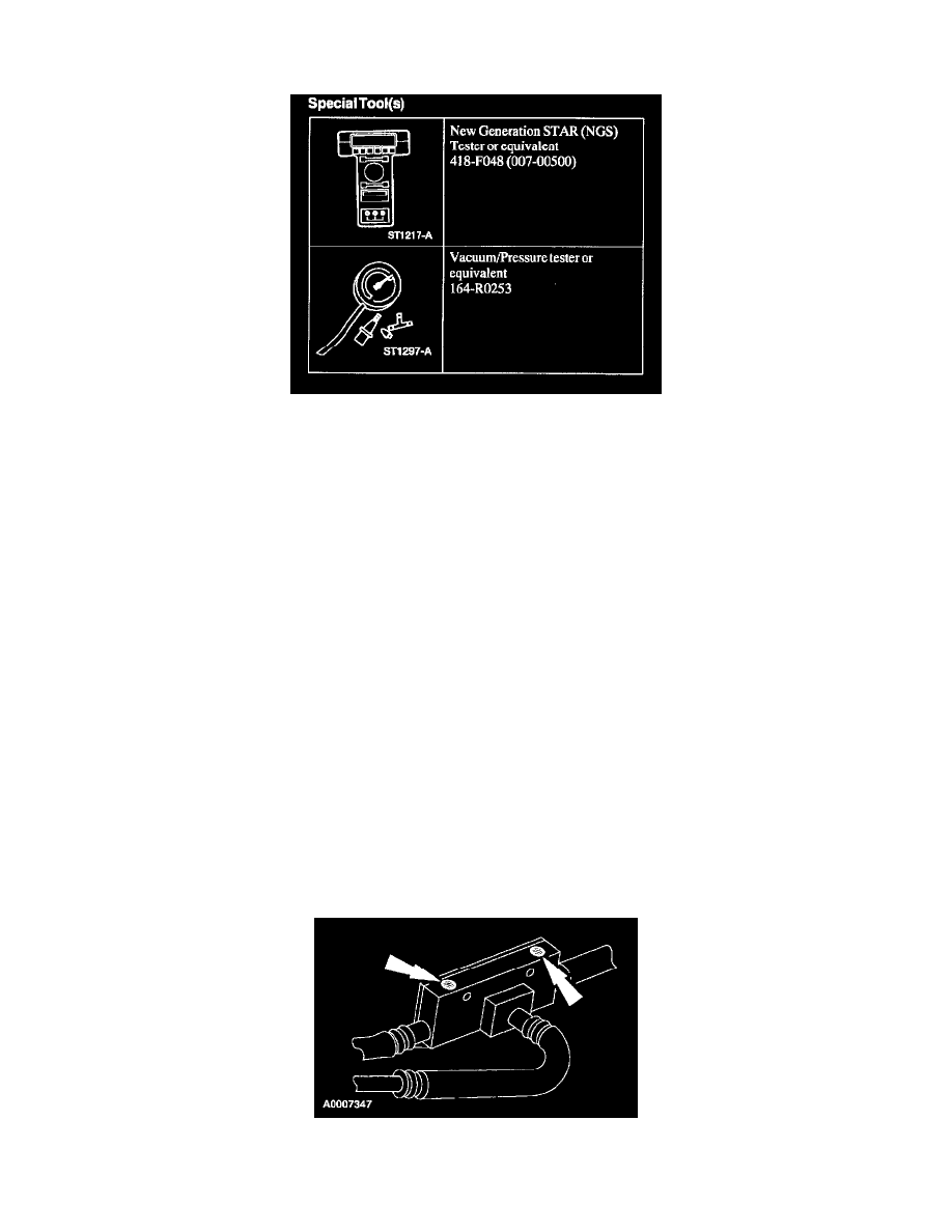
8. Locate the two adjustment screw holes on the top of the tuning tee assembly, remove any sealant and access the adjustment screws.
WARNING: NEVER REMOVE THE TUNING TEE ADJUSTMENT SCREWS WHILE THE LOW PRESSURE FUEL LINES ARE