
F 150 Super Crew 4WD V8-5.4L Prop SOHC VIN Z (2003)
DISLODGED FROM THE TUNING TEE SERIOUS PERSONAL INJURY MAY RESULT.
9. Position both tuning tee adjustment screws to their 'neutral' state by turning them counterclockwise with a slotted screwdriver until the screw head
tops are flush with the top of the tuning tee and then turning them clockwise two complete turns.
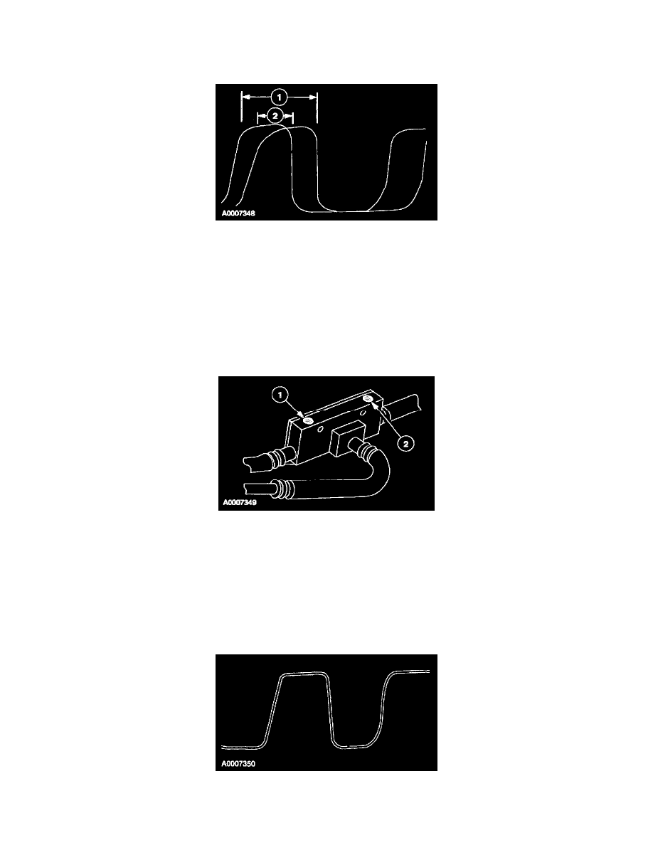
10. With the engine at idle speed and the transmission gear in the park position, select the NGS GRAPH option. Record ten seconds of data from
PCM PIDs O2S11 and O2S21 (1 and 2). Retrieve the recorded data and identify which of the OS2 signals displays the longest high state time (1).
WARNING: THIS STEP REQUIRES TWO PEOPLE WHILE THE VEHICLE IS RUNNING, IN GEAR, AND THE ENGINE
ACCELERATED. BE SURE THAT THE PARKING BRAKE IS FULLY SET AND THE WHEELS ARE CORRECTLY CHOCKED. TAKE
ALL NECESSARY PRECAUTIONS TO AVOID INJURY AND PROPERTY OR EQUIPMENT DAMAGE.
11. Use an assistant in the driver seat to repeat step 6. Obtain and hold the 'tuning point' vacuum value.
12. Select the NGS GRAPH option and record ten seconds of data from PCM PIDs O2S11 and O2S21. Allow the accelerator to return to the idle
position and place the transmission gear in the park position.
13. Retrieve the recorded data and identify which of the OS2 signals displays the longest high state time as in step 10.
14. Determine which of the tuning tee adjustment screws requires adjustment. This is the only screw to be adjusted throughout the entire tuning tee
procedure and is determined by the following: The PCM PID O2S11 data reflects the upstream bank 1 O2S and is adjusted with the passenger side
tuning tee adjustment screw (1). The PCM PID O2S21 data reflects the upstream bank 2 O2S and is adjusted with the driver side tuning tee
adjustment screw (2). To reduce the PCM PID O2S11 or O2S21 high state time the corresponding adjustment screw is turned clockwise and to
increase the high state time the adjustment screw is turned counterclockwise.
15. Turn the tuning tee adjustment screw identified in step 13 one complete turn clockwise and repeat steps 10 through 12.
16. Retrieve and compare the current graphed PCM PIDs O2S11 and O2S21 data with the previous data. If the determined PCM O2S PID from the
previous graphed data continues to have the longer high state time, repeat steps 15 and 16.
17. If the determined PCM O2S PID from the previous graphed data now has a shorter high state time, turn the corresponding tuning tee adjustment
screw counterclockwise 1/2 turn and repeat steps 10 through 12.
18. Retrieve and compare the current recorded graphed PCM PIDs O2S11 and O2S21 data. If necessary, continue to turn the same adjustment screw
by 1/4 and 1/8 turn increments clockwise or counterclockwise as described in step 14 repeating steps 10 through 12 with each adjustment until
both O2S PIDs display equal high state time.