
F 250 2WD HD Pickup V8-7.3L DSL Turbo VIN F (1997)
adjusting nuts must be backed off or the rocker arm and shaft assembly must be loosened sufficiently to free the camshaft. After checking the
camshaft end play, resecure valve train components.
2. Zero dial indicator. Pull camshaft forward and release it. Compare dial indicator reading with specifications. If end play is excessive, replace
camshaft thrust plate.
3. Remove dial indicator.
4. After replacing thrust plate, check end play again. If it is still out of specified range, inspect camshaft and cylinder block for excessive wear.
Runout
NOTE: Check camshaft journals for out of round before checking for runout; an out of round condition on the center journal could be confused for an
excess runout condition.
1. Set suitable V-blocks on surface plate. Support outer camshaft journals on V-blocks.
2. Set up Dial Indicator with Bracketry TOOL-4201 -C or equivalent to check center bearing journal.
3. Zero dial indicator.
4. Slowly rotate camshaft to determine overall runout. If runout exceeds 0.03 mm (0.0012 in.), replace camshaft.
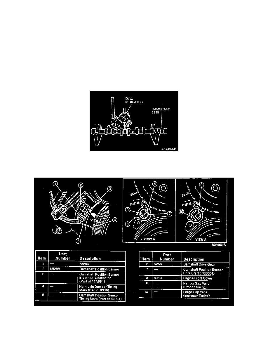
Timing-Front Cover Installed
1. Align timing mark on crankshaft vibration damper with the timing mark on the camshaft position sensor (CMP sensor).
2. Remove camshaft position sensor electrical connector from camshaft position sensor.
3. Remove screw retaining the camshaft position sensor to the engine front cover. Remove the camshaft position sensor.
4. Verify Top Dead Center (TDC) for No.1 cylinder. Inspect camshaft position sensor bore in the engine front cover. Verify that the narrow gap vane
on the camshaft drive gear is located in the middle of the bore.