
F 250 2WD Pickup V8-351 5.8L (1982)
2.
Locate the template on the bottom flange of the radius arm. Figures 7 and 8 show a typical arm modification for the F150 4x2 right hand arm. One
template per vehicle model is used to modify both the right and left hand arms. When modifying the right hand arm, position the template with the
printed side downward. The F Series template locates off of one of two existing holes in the arm. The Ranger template is shaped to match the
contour of the edges of the arm.
3.
With template secure, make a punch mark at the center of the small hole inside the printed circle. Scribe the slot printed/cut-out on the template
and die-grind out the slot at the axle-attaching hole the same size as the slot in the template and de-burr the surface avoiding rounding the edges of
the slot.
4.
Drill a 0.228 inch diameter hole at the punch mark. Use this hole to mount the cam with the 1/4-20 self-tapping screw supplied.
Figure 9
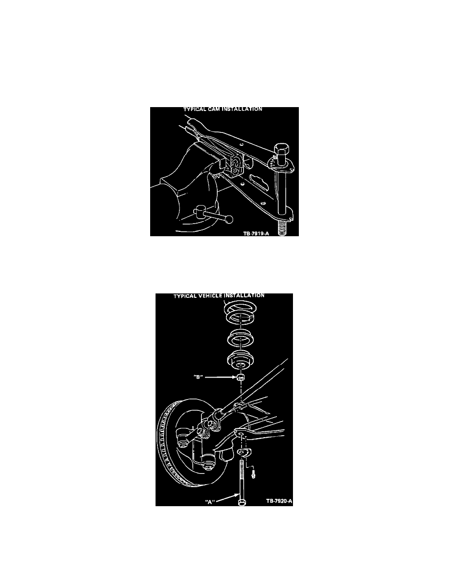
5.
Figure 9 shows a typical cam installation. Each hole in the cam represents a 1/2 degree caster increase. A caster increase of approximately 2
degrees for F-150 4x2 for example will be obtained by mounting the cam with the self-tapping screw in
the No. 2 hole of the cam to the lower flange of the radius arm.
Figure 10
6.
Figure 10 shows a typical F-100/150 4x2 vehicle installation. TORQUE BOLT A AND NUT B TO:
160 to 220 ft.lbs.
Ranger 4x2