
F 250 2WD Pickup V8-351 5.8L (1982)
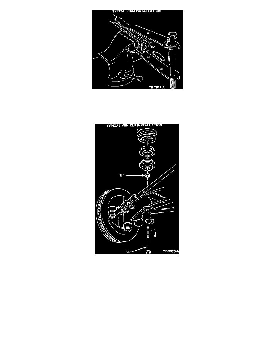
Figure 9
5.
Figure 9 shows a typical cam installation. Each hole in the cam represents a 1/2 degree caster increase. A caster increase of approximately 2
degrees for F-150 4x2 for example will be obtained by mounting the cam with the self-tapping screw in
the No. 2 hole of the cam to the lower flange of the radius arm.
Figure 10
6.
Figure 10 shows a typical F-100/150 4x2 vehicle installation. TORQUE BOLT A AND NUT B TO:
160 to 220 ft.lbs.
Ranger 4x2
270 to 330 ft.lbs.
F Series
7.
Reset front wheel toe to zero after installation is complete.
The following are methods for adjusting caster on vehicles with stamped front axles:
1.
TSB No. 82-10-18 provides a 1/2 degree adjustment per side to correct a caster split of 1 degree.
2.
For caster splits greater than 1 degree the axleattaching hole in the radius arm can be slotted to allow more axle rotation for increasing caster.
SLOT ONLY ONE HOLE IN THE UPPER EAR OF THE RADIUS ARM (AT THE SPRING SEAT). DO NOT SLOT THE LOWER EAR OF
ANY RADIUS ARM WITH STAMPED AXLES. Slotting the upper hole rearward 1/8 inch will provide approximately 1 degree of caster
increase. With the slotted radius arm and axle loosely assembled, twist the axle (top of axle rearward) while torquing the axle-to-radius arm joint
before the spring seat is installed. Verify correct torque with a torque wrench - do not depend on an impact wrench for final torque.