
F 250 2WD Pickup V8-351 5.8L (1982)
Front Steering Knuckle: Service and Repair
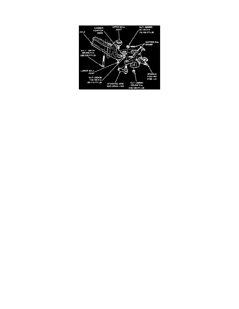
With Stamped Front I Beam
Spindle
REMOVE
1. Raise the front of the vehicle and install safety stands.
2. Remove the wheel and tire assembly.
3. Remove the caliper assembly from the rotor and hold it out of the way with wire.
4. Remove the dust cap, cotter pin, nut retainer, nut, washer, and outer bearing, and remove the rotor from the spindle.
5. Remove inner bearing cone and seal. Discard the seal.
6. Remove brake dust shield.
7. Disconnect the steering linkage from the integral spindle and spindle arm by removing the cotter pin and nut and then removing the tie rod end
from the spindle arm with TOOL 3290-C.
8. Remove the cotter pin from the upper and lower ball joint studs. Remove the nut from the upper ball joint stud. Loosen the lower nut to the end of
the lower stud.
9. Strike the inside area of the spindle to pop the ball joints loose from the spindle.
CAUTION: Do not use a pickle fork to separate the ball joint from the spindle as this will damage the seal and the ball joint socket.
10. Remove the spindle.
INSTALL
1. Prior to assembly, make sure the upper and lower ball joint seals are in place.
2. Place the spindle over the ball joints.
3. Install the nut on the lower ball joint stud and partially tighten to 41 Nm (30 ft lb).
4. Install the camber adapter in the upper spindle over the upper ball joint stud. Be sure the adapter is aligned properly. If camber adjustment is
necessary, special adaptors must be installed.
5. Install the nut on the upper ball joint stud. Hold the camber adaptor with a wrench to keep the ball stud from turning. If the ball stud turns, tap the
adaptor lightly into the spindle. Tighten the nut to 116-136 Nm (85-101 ft lbs) and continue tightening the castellated nut until it lines up with the
hole in the stud. Install the cotter pin.
6. Retighten lower nut to 190-244 Nm (140-180 ft lb).
7. Install the dust shield.
8. Pack the inner and outer bearing cone with a lithium-base grease, Multi-Purpose Long-Life Lubricant, C1AZ-19590-B (ESA-M1C75-B) or
equivalent. Use a bearing packer. If a bearing packer is unavailable, pack the bearing cone by hand working the grease through the cage behind the
rollers.
9. Install the inner bearing cone and seal. Install the hub and rotor on the spindle.
10. Install the outer bearing cone, washer, and nut. Adjust bearing end play and install the nut retainer, cotter pin and dust cap.
11. Install the caliper.
12. Connect the steering linkage to the spindle. Tighten the nut to 94-135 Nm (70-100 ft lbs) and advance the nut as required for installation of the
cotter pin.
13. Install the wheel and tire assembly.
14. Lower the vehicle.
15. Check and, if necessary adjust the toe setting.