
F 250 2WD Pickup V8-6.9L DSL (1985)
Fuel Gauge Sender: Description and Operation
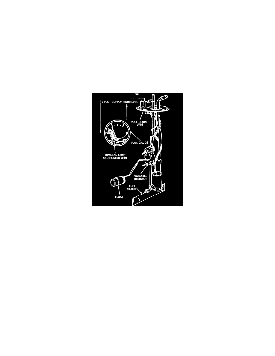
DESCRIPTION AND OPERATION FUEL LEVEL INDICATING SYSTEM
The fuel indicating system is a bimetal-resistance type system. It consists of an instrument voltage regulator, fuel indicator (gauge) mounted in the
instrument cluster and a sender located in the fuel tank,
INSTRUMENT VOLTAGE REGULATOR
The instrument voltage regulator (IVR) used with the fuel indicator (gauge) controls and maintains an average pulsating voltage of 5.0 volts at the gauge
terminals.
FUEL INDICATOR (GAUGE)
The fuel indicator gauge pointer is attached to a wire wound bimetal strip which when heated by the flow of electrical current controlled by the sender
unit, produoes the appropriate indication.
Fuel Indicating System Using A Bimetal Gauge - Typical
FUEL SENDER
The fuel sender consists of a variable screened resistor made up of a ceramic substrate. It is controlled by the action of an attached float in the fuel tank.
When the fuel level is low, resistance in the sender is high and allows only a low current to flow through the indicator (gauge) windings, causing the
pointer to move a short distance. When the fuel level is high, the resistance in the sender is low and allows a higher current flow and a greater heating
effect causing the pointer to move a greater distance.