
A/T Vacuum Regulator Valve - Adjustment Procedure
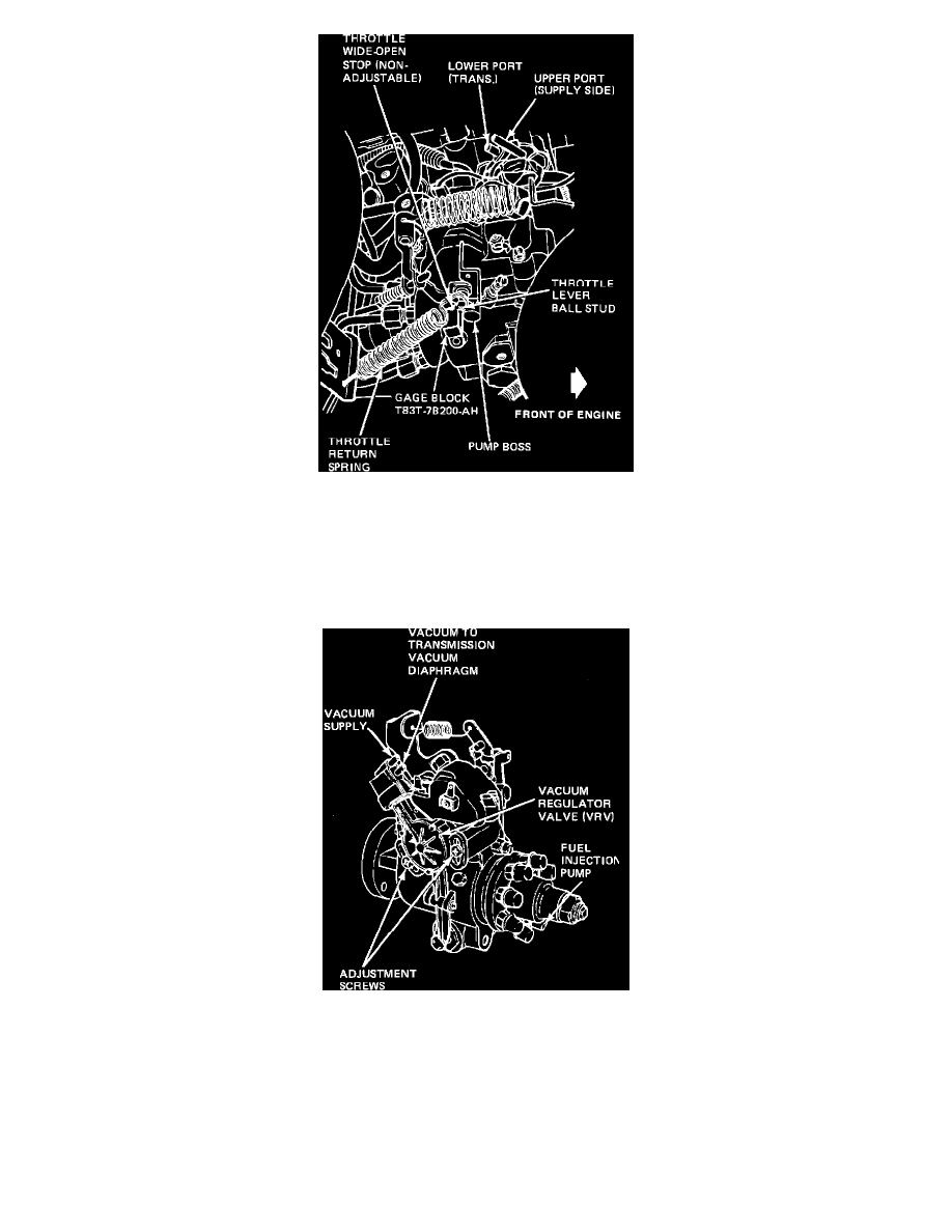
Figure 31 - VRV GAUGE BLOCK INSTALLATION
6.
Apply 20 inches of vacuum to the VRV and maintain. It will be necessary to pump the vacuum up as it bleeds off. Cycle the throttle lever 5
times from idle to wide-open throttle with vacuum applied, Insert the gauge block, T83T-7B200-AH (0.515 inch), between the pump boss
and the throttle wide-open stop (Figure 31). The throttle return spring, as repositioned in Step 3 above, will hold the throttle lever stop against
the gauge block. The vacuum gauge attached to the lower port of the VRV should indicate 6-8 inches of vacuum. If the vacuum reading is not
correct, adjust the VRV to achieve a reading of 7 inches of vacuum.
Figure 30 VACUUM REGULATOR VALVE (VRV) - E-250 - E-350, F-250 - F-350 WITH 6.9L DIESEL ENGINE
7.
To adjust, loosen the two adjustment screws that attach the VRV to the fuel injection pump (Figure 30). Rotate the VRV until the proper
vacuum is obtained. Tighten the two adjusting screws to 8- 10.5 Nm (75-90 in.lbs.) when the proper vacuum reading is obtained. If the VRV
cannot be adjusted to obtain the proper vacuum, replace the VRV and repeat procedure in Step 3.
8.
Remove the gauge block.
9.
Reattach the throttle return spring and throttle cable.
10.
Again, apply 20 inches of vacuum to the VRV and while maintaining vacuum, cycle the throttle lever from idle to wide-open throttle 5 times.