
F 250 2WD Pickup V8-7.3L DSL (1990)
h.
If the pad clearances are NOT WITHIN SPECIFICATION, file the shoe tabs.
WARNING:
USE SAFETY GLASSES WHEN FILING SHOE TABS.
^
File material, removing equal amounts from both sides or ends. (See Figure 3.)
CAUTION: DO NOT GRIND. IT IS POSSIBLE TO REMOVE TOO MUCH MATERIAL WHEN GRINDING SHOES.
^
Check the tab clearances and install anti-rattle clip on the lower pad tab, Figure 2.
2.
Apply a light coat of lubricant (D7AZ-19590-A) to the knuckle top and bottom pad groove and caliper rails.
CAUTION: MAKE SURE THE LUBRICANT DOES NOT GET ON THE ROTORS, LININGS, OR ON THE CALIPER PISTON BOOTS.
NOTE:
FOR BRONCOS BUILT AFTER FEBRUARY 1990, THE RIGHT HAND RADIUS ARM PIVOT BRACKET IS BOLTED ON. REFER TO
STEP 4. FOR ALL VEHICLES BUILT PRIOR TO FEBRUARY 1990, USE STEP 3.
3.
Replace the right side radius arm bracket fasteners (Vehicles built prior to February 1990. This does not apply to F-350 4X4 or F-250 4X4
because no radius arms are used).
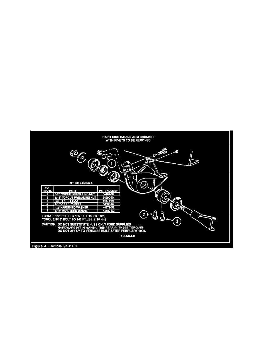
NOTE:
THE SPECIFIED FASTENERS AND TORQUE REQUIREMENTS MUST BE USED. SEE FIGURE 4 FOR A DESCRIPTION OF PARTS
CONTAINED IN THE RIGHT SIDE RADIUS ARM BRACKET KIT (E8TZ-3L095-A). REPLACE ONE RIVET AT A TIME TO
MAINTAIN BRACKET LOCATION.
Figure 4
a.
Start with rivet number one (1). Drill an 1/8" hole through the middle of the rivet. See Figure 4.
b.
Drill the same hole with an 11/32" drill.
c.
Use an air chisel to remove the rivet head.
d.
Drive the rivet out with a punch.
e.
Line ream the rivet hole in the frame web to a 1/2" diameter. See Figure 4, reference rivet # 1.