
F 250 2WD Pickup V8-7.3L DSL (1990)
Diode Trio: Testing and Inspection
TEST PROCEDURES
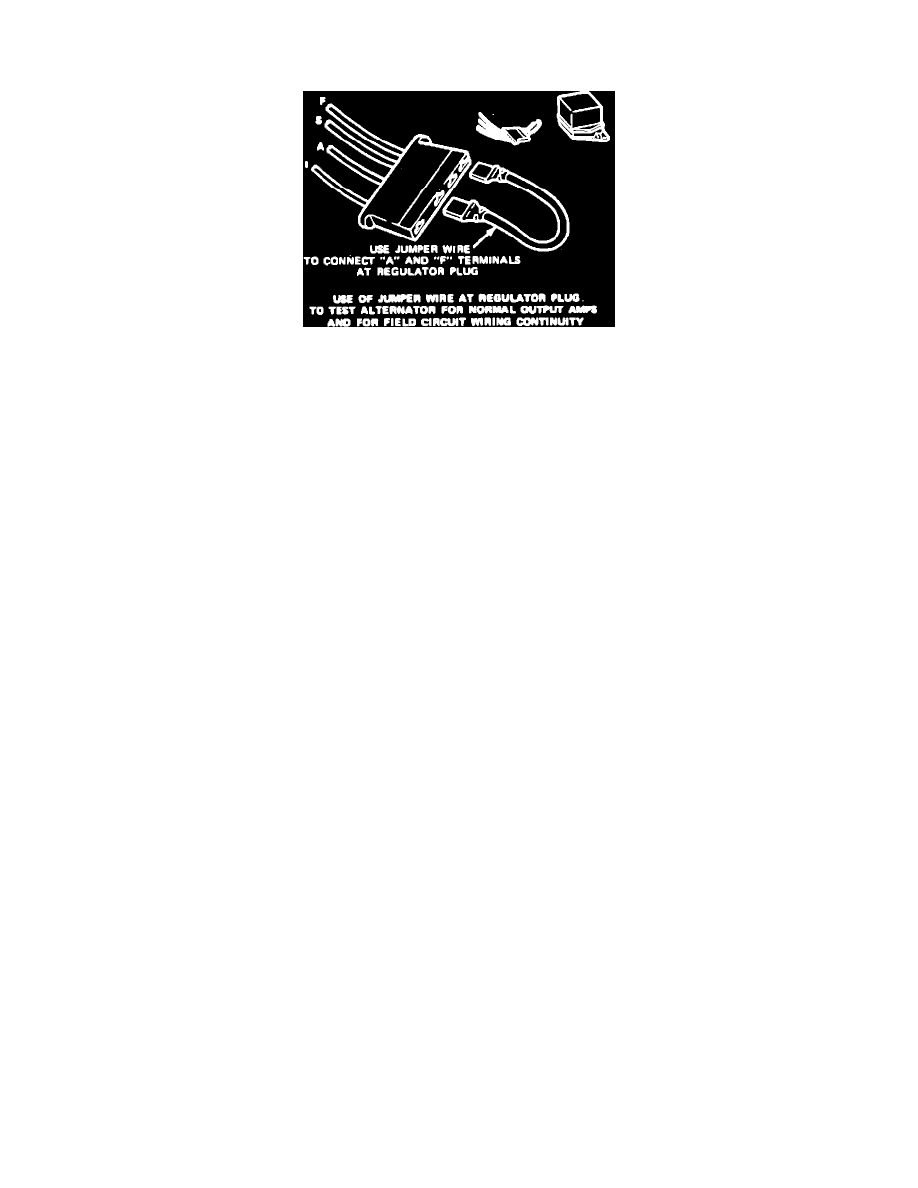
Fig. 9 Regulator Plug. Jumper Wire Connector
1.
Disconnect electric choke, if equipped.
2.
Disconnect voltage regulator wiring connector.
3.
Connect a jumper wire between the ``A'' and ``F'' terminals of voltage regulator wiring connector, Fig. 9.
4.
Connect voltmeter to battery clamps. Then start and idle engine.
5.
Observe and note voltmeter reading.
6.
Move voltmeter positive lead to the alternator ``S'' terminal and note voltage reading.
TEST RESULTS
1.
If voltmeter reading is within 1/2 of battery voltage, diodes are satisfactory.
2.
If voltmeter reading is approximately 1.5 volts, the alternator has a shorted negative diode or a grounded stator winding.
3.
If voltmeter reading is approximately 1.5 volts less than battery voltage, the alternator has a shorted positive diode.
4.
If voltage reading is approximately 1 to 1.5 volts less than 1/2 battery voltage, the alternator has an open positive diode.
5.
If voltage reading is 1 to 1.5 volts above 1/2 battery voltage, the alternator has an open negative diode.
6.
Reconnect electric choke into circuit after tests are completed, if equipped.