
F 250 2WD Pickup V8-7.3L DSL (1990)
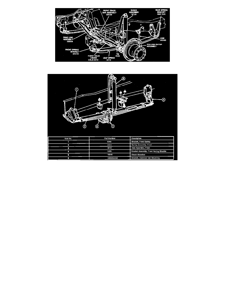
Fig. 3 One Piece Solid I-beam Axle
Fig. 4 One Piece Solid I-beam Axle
Twin I-Beam Axle
The F-Series and E-Series vehicles use two I-beam type axles, one for each front wheel. One end of each axle is attached to the spindle and a radius
arm and the other end is attached to a frame pivot bracket on the opposite side of the vehicle Figs. 1 and 2. Each spindle is held in place on the axle by
ball joints or a spindle bolt which pivots in bushings pressed in the upper and lower ends of the spindle. On models equipped with spindle bolts, a thrust
bearing is installed between the lower end of the axle and the spindle to support the load on the axle. On all models, a spindle arm is installed on each
spindle for attachment to the steering linkage. The F-super duty vehicle uses a one piece solid I-beam type axle. The axle is attached by two leaf springs,
which bolt to spring brackets on both frame side rails Fig. 3. The F-Super duty commercial chassis and motorhome chassis models use two leaf springs
attached to a single solid I-beam front axle. The springs are attached to the frame side rail using a fixed bracket at the front and a moveable shackle at the
rear, Fig. 4.