
F 250 2WD Pickup V8-7.3L DSL (1990)
Spindle: Service and Repair
Spindle
Ball Joint Service
REMOVE
1. Raise the front of the vehicle and install safety stands.
2. Remove the wheel and tire assembly.
3. Remove the caliper assembly from the rotor and hold it out of the way with wire.
4. Remove the dust cap, cotter pin, nut retainer, nut, washer, and outer bearing, and remove the rotor from the spindle.
5. Remove inner bearing cone and seal. Discard the seal.
6. Remove brake dust shield.
7. Disconnect the steering linkage from the integral spindle and spindle arm by removing the cotter pin and nut and then removing the tie rod end
from the spindle arm with Tie Rod End Remover, TOOL-3290-D or equivalent.
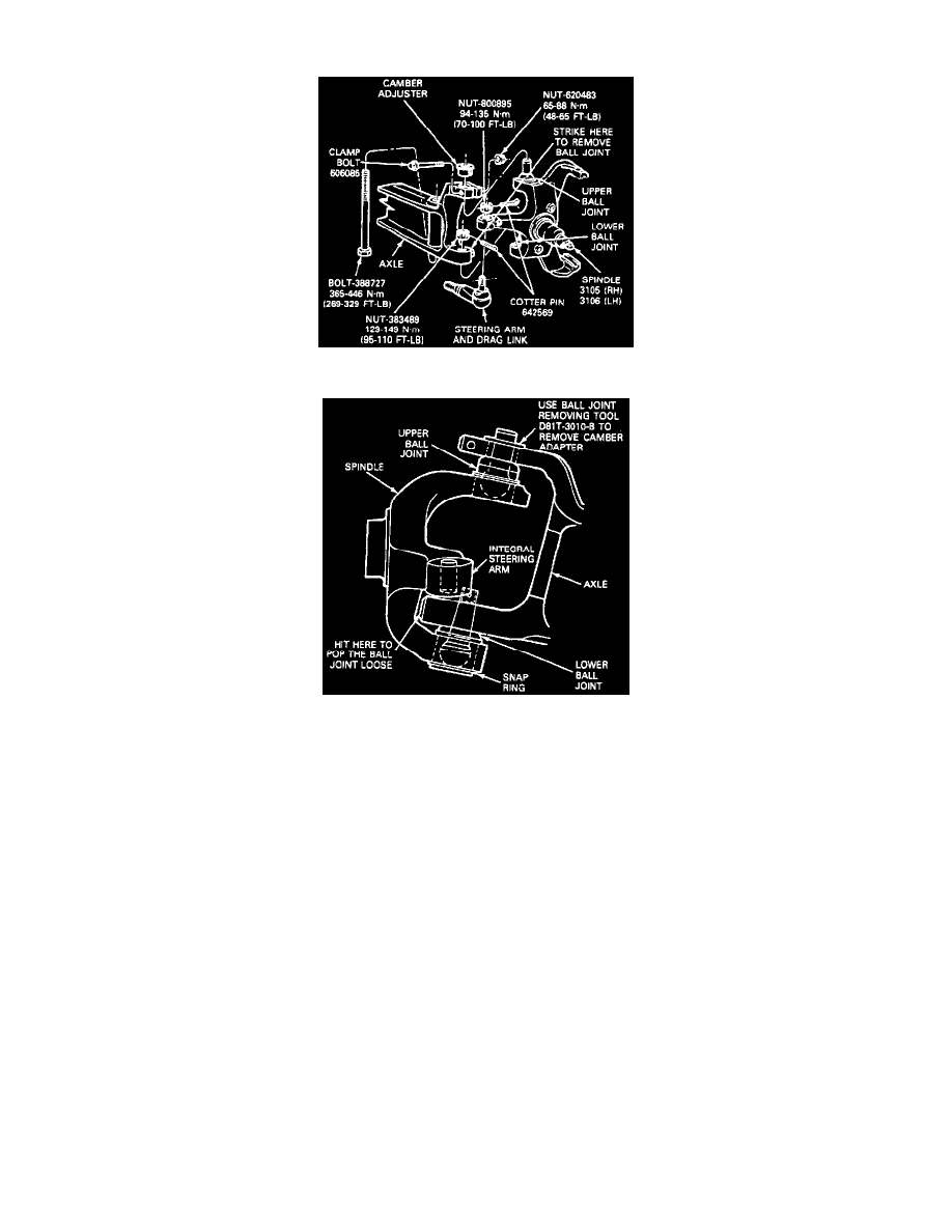
8. Remove the cotter pin and castellated nut from the lower ball joint stud.
9. Remove the nut from the axle clamp bolt and remove the bolt from the axle.
10. Remove the camber adjuster from the upper ball joint stud and axle beam.
11. Strike the inside area of the axle to pop the lower ball joints loose from the axle beam.
CAUTION: Do not use a pickle fork to separate the ball joint from the axle as this will damage the seal and the ball joint socket.
12. Remove the spindle and ball joint assembly from the axle.
INSTALL
1. Place the spindle and the ball joints into the axle.
2. Install the nut on the lower ball joint stud and tighten to 129-149 Nm (95-110 ft lb), and continue tightening the castellated nut until it lines up
with the hole in the stud. (Install the cotter pin.)
3. Install the camber adjuster in the upper spindle over the upper ball joint stud. Be sure the adjuster is aligned properly. If camber adjustment is
necessary, special adjusters must be installed.
4. Install the clamp bolt and nut into the axle boss. Tighten the nut to 65-88 Nm (48-65 ft lb).