
F 250 2WD Pickup V8-7.3L DSL (1990)
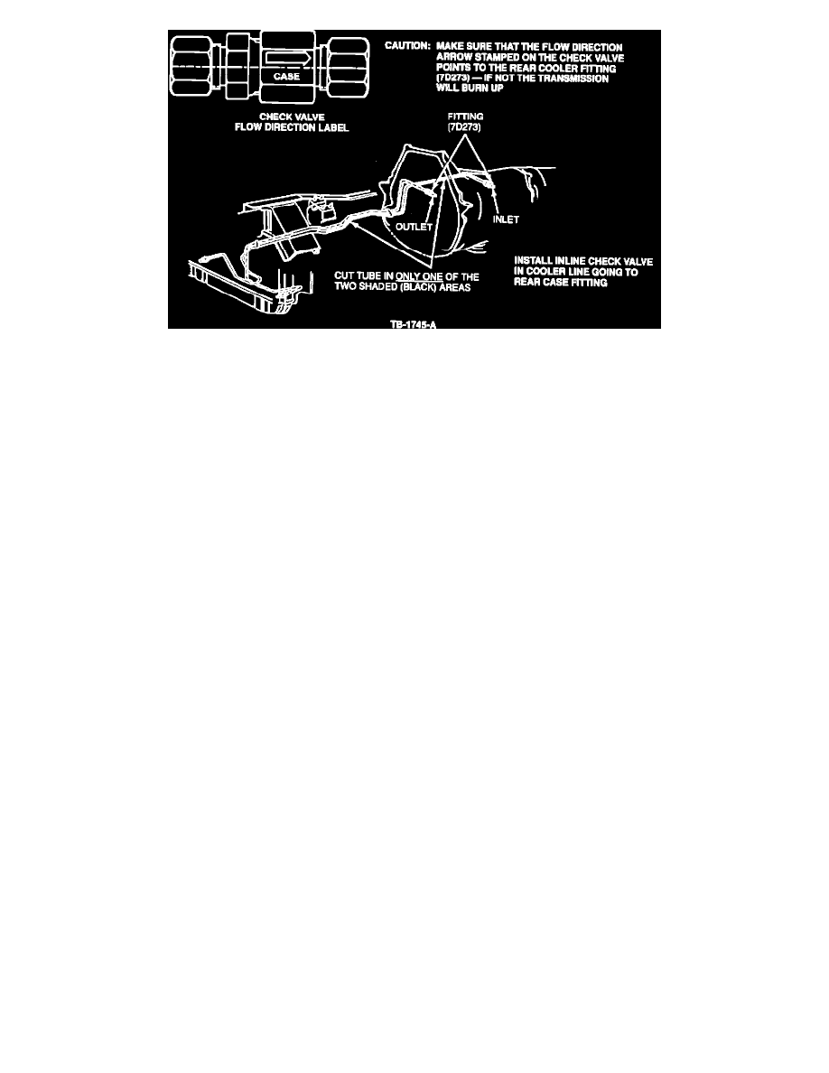
Figure 3
CHECK VALVE INSTALLATION
1.
Select the check valve location in the cooler-to-case rear fitting line, Figure 3.
CAUTION:
IT IS MANDATORY THAT THE COOLER-TO-CASE LINE BE POSITIVELY IDENTIFIED OR A TRANSMISSION FAILURE
WILL RESULT
2.
Clean a section about three (3) inches long around the chosen location with "Scotchbrite", steel wool or sandpaper to remove all rust and dirt.
3.
Cut the line at one end of the check valve location. Use a tubing cutter and file off any burrs or ragged edges.
4.
Install check valve with the arrow pointing to the rear case fitting, Figure 3.
CAUTION:
IF THE ARROW IS AIMED WRONG, THE TRANSMISSION WILL FAIL.
5.
Tighten the tube nut to securely locate the check valve.
6.
Hold the free end of the line alongside the check valve. Mark it so that, when cut, the end will seat completely in the check valve.
NOTE:
IT IS BETTER FOR THE LINE TO BE SLIGHTLY LONG SO THAT THE CHECK VALVE WILL BE IN COMPRESSION. IF THE
LINE IS CUT SHORT, IT WILL TEND TO PULL OUT OF THE CHECK VALVE.
7.
Tighten the tube nuts and run the engine while checking for leaks.
8.
Spray with solvent to remove residual oil from installation.
9.
Drive the vehicle, warming the transmission up to normal operating temperature.
10.
Check for leaks and tube tightness.
PART NUMBER
PART NAME
CLASS
FOTZ-7D 174-A
Check Valve Assy.
B
OTHER APPLICABLE ARTICLES: None
WARRANTY STATUS:
Eligible Under Basic Warranty Coverage, Powertrain Warranty Coverage
OPERATION
DESCRIPTION
TIME
901811A
Install Check Valve & Road
0.7 Hr.
Test
DEALER CODING
BASIC PART NO. CONDITION CODE
7902
53
OASIS CODES:
503000, 510000