
F 250 2WD Pickup V8-7.3L DSL Turbo VIN F (1994)
Axle Beam: Description and Operation
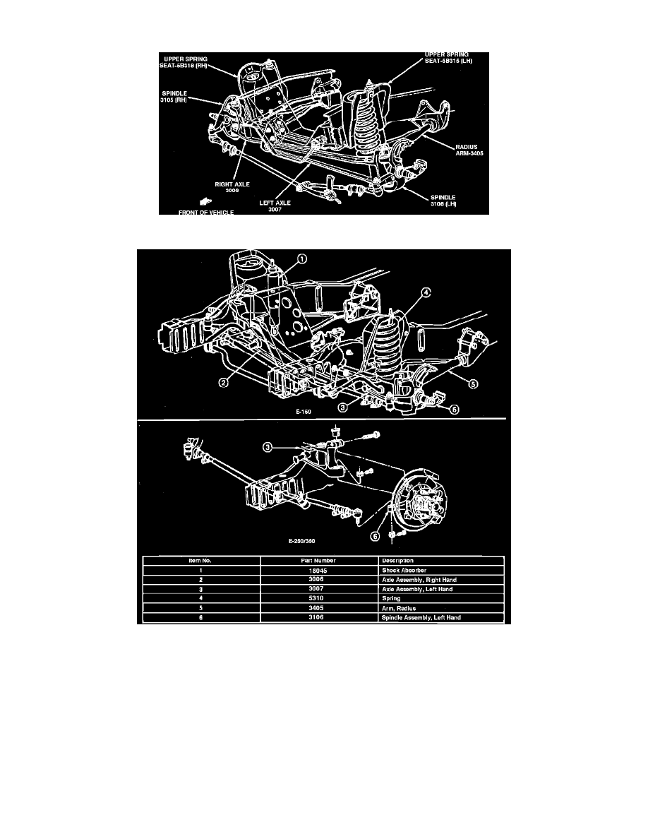
Fig. 1 Twin I-beam Front Axle
Fig. 2 Twin I-beam Front Axle
These vehicles use two I-beam type axles, one for each front wheel. One end of each axle is attached to the spindle and a radius arm and the other end is
attached to a frame pivot bracket on the opposite side of the vehicle.
Each spindle is held in place on the axle by ball joints or a spindle bolt which pivots in bushings pressed in the upper and lower ends of the spindle. On
models equipped with spindle bolts, a thrust bearing is installed between the lower end of the axle and the spindle to support the load on the axle. On all
models, a spindle arm is installed on each spindle for attachment to the steering linkage.