
F 250 2WD Super Duty V10-6.8L (2009)
Trailer Brake Control Module: Initial Inspection and Diagnostic Overview
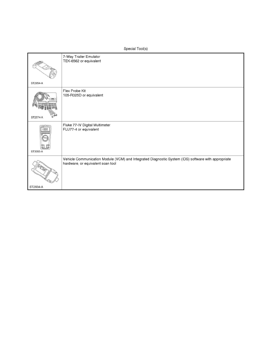
Special Tools Used With Diagnostics
Auxiliary Brake System - Trailer Brake Control (TBC) Module
Principles of Operation
Auxiliary Brake System - Trailer Brake Control (TBC) Module
Principles of Operation
The Trailer Brake Control (TBC) module is an integrated electronic control device that is designed to provide variable braking power to the
electric-actuated drum brakes on a towed trailer (1 to 4 axles only). The braking energy that is provided to the trailer is varied with a Pulse Width
Modulated (PWM) signal that switches between 0 volt and battery voltage, the higher the duty cycle the more braking power available.
The TBC module receives information from 3 different brake pedal inputs: the Brake Pedal Position (BPP) switch, the brake pressure switch (also
known as the speed control deactivation switch) and the brake pressure transducer.
The BPP switch is mounted on the brake pedal bracket and switches on or off depending on the brake pedal position. The brake pressure switch is
mounted on the bottom of the master cylinder near the front and switches on or off depending on the pressure applied on the brake pedal. The TBC
module receives both the BPP and the brake pressure switch information over the High Speed Controller Area Network (HS-CAN) bus from the PCM.
The brake pressure transducer is mounted on the bottom of the master cylinder near the rear and sends a variable voltage to the TBC module depending
on the pressure applied to the brake pedal. The TBC module receives this information directly from the pressure transducer.
The TBC module receives information through the HS-CAN bus. These inputs are from the PCM, the Instrument Cluster (IC) and the ABS module. The
information sent out from the TBC module is through the IC and is displayed on the message center.
To adjust the gain setting up or down, the TBC module faceplate provides the driver with control buttons which determine the maximum power output
sent to the 14-pin connector. The TBC module faceplate also provides a manual control lever to manually apply the trailer brakes, independent of the
vehicle brakes, to calibrate the gain setting to the specific trailer loading and road conditions. Note that when the manual control is activated, both the
center high-mounted stoplamp and the trailer brake lamps illuminate. If a trailer is not connected and the manual control lever is activated, the vehicle
center high-mounted stoplamp will still illuminate.