
F 250 2WD Super Duty V10-6.8L (2009)
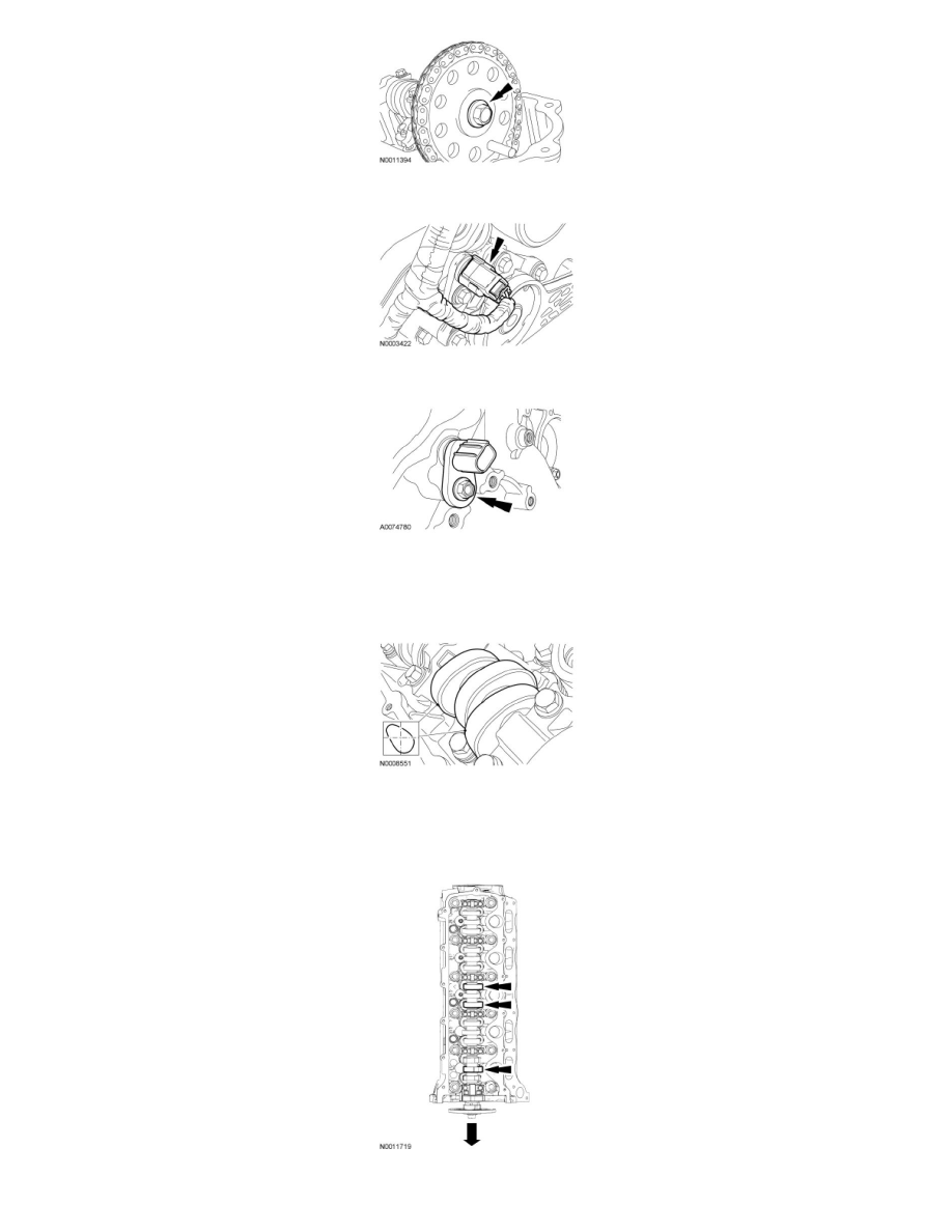
4. Disconnect the Camshaft Position (CMP) sensor electrical connector.
5. Remove the bolt and the CMP sensor.
6. NOTE: If the camshaft lobes are not exactly positioned as shown, the crankshaft will require one full additional rotation to 12 o'clock.
The No. 1 cylinder camshaft exhaust lobe must be coming up on the exhaust stroke. Verify by noting the position of the 2 intake camshaft lobes
and the exhaust lobe on the No. 1 cylinder.
7. NOTICE: If the components are to be reinstalled, they must be installed in the same positions. Mark the components for installation into
the original locations. Failure to follow these instructions may result in engine damage.
Remove only the 3 camshaft roller followers shown in the illustration from the RH cylinder head.
8. NOTICE: The camshaft roller followers must be installed in their original locations. Record camshaft roller follower locations. Failure to