
F 250 2WD Super Duty V10-6.8L (2009)
-
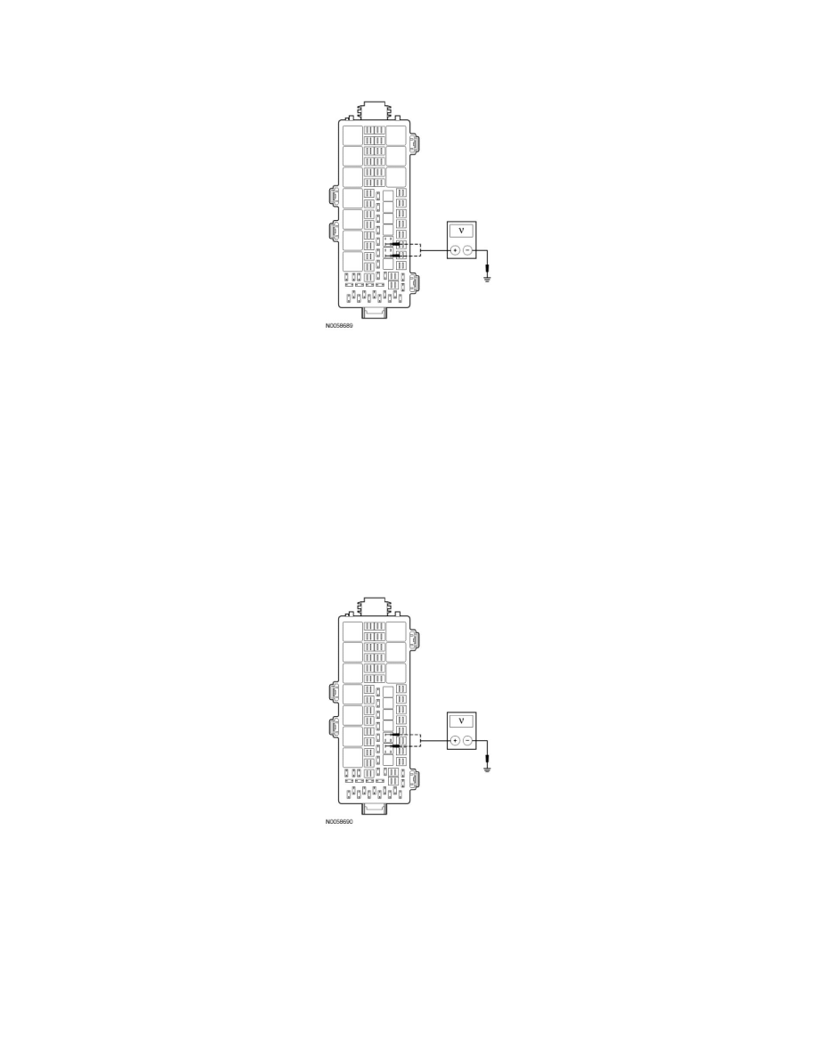
While applying the brake pedal, measure the voltage between the trailer tow LH stop/turn relay pin 1, circuit CLS18 (GY/BN), BJB face side and
ground; or between the trailer tow RH stop/turn relay pin 1, circuit CLS19 (VT/OG), BJB face side and ground.
-
Is the voltage greater than 10 volts?
Yes
GO to Z5.
No
REPAIR the circuit in question. TEST the system for normal operation.
-------------------------------------------------
Z5 CHECK THE TRAILER TOW STOP/TURN RELAY BJB VOLTAGE SUPPLY
-
Measure the voltage between the trailer tow LH stop/turn relay pin 3, BJB face side and ground; or between the trailer tow RH stop/turn relay pin
3, BJB face side and ground.
-
Is the voltage greater than 10 volts?
Yes
GO to Z6.
No
VERIFY the BJB fuse 34 (25A) is OK. If OK, INSTALL a new BJB. TEST the system for normal operation.
If not OK, REFER to the Wiring Diagrams to identify the possible causes of the circuit short.
-------------------------------------------------