
F 250 2WD Super Duty V10-6.8L (2009)
-
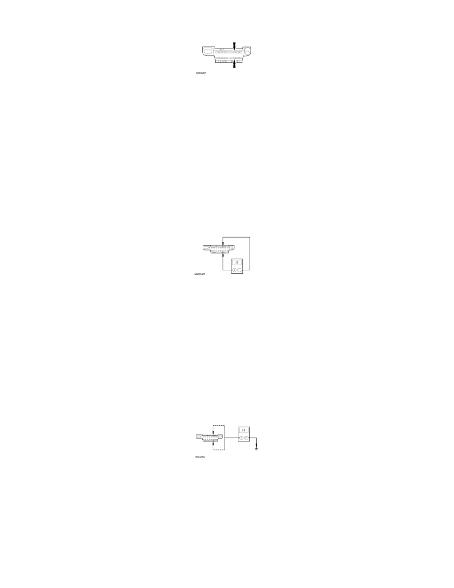
Inspect DLC pins 6 and 14 for damage.
-
Are DLC pins 6 and 14 OK?
Yes
GO to S2.
No
REPAIR the DLC as necessary. CLEAR the DTCs. REPEAT the network test with the scan tool.
-------------------------------------------------
S2 CHECK THE HS-CAN TERMINATION RESISTANCE
-
Ignition OFF.
-
Disconnect: Negative Battery Cable.
-
Measure the resistance between the DLC C251-6, circuit VDB04 (WH/BU), harness side and the DLC C251-14, circuit VDB05 (WH), harness
side.
-
Is the resistance between 54 and 66 ohms?
Yes
GO to S3.
No
Go To Pinpoint Test R. See: Pinpoint Test R: No ISO 9141 Network Communication
-------------------------------------------------
S3 CHECK THE HS-CAN (+) AND HS-CAN (-) CIRCUITS FOR A SHORT TO GROUND
-
Measure the resistance between the DLC C251-6, circuit VDB04 (WH/BU), harness side and ground; and between the DLC C251-14, circuit
VDB05 (WH), harness side and ground.
-
Are the resistances greater than 5,000 ohms?
Yes
CONNECT the negative battery cable. GO to S4.
No
Go To Pinpoint Test R. See: Pinpoint Test R: No ISO 9141 Network Communication
-------------------------------------------------
S4 CHECK THE HS-CAN (+) AND HS-CAN (-) CIRCUITS FOR A SHORT TO VOLTAGE