
F 250 2WD Super Duty V10-6.8L (2009)
VDB05 (WH), harness side.
-
Are the resistances less than 5 ohms?
Yes
GO to T31.
No
REPAIR the circuit in question. CLEAR the DTCs. REPEAT the network test with the scan tool.
-------------------------------------------------
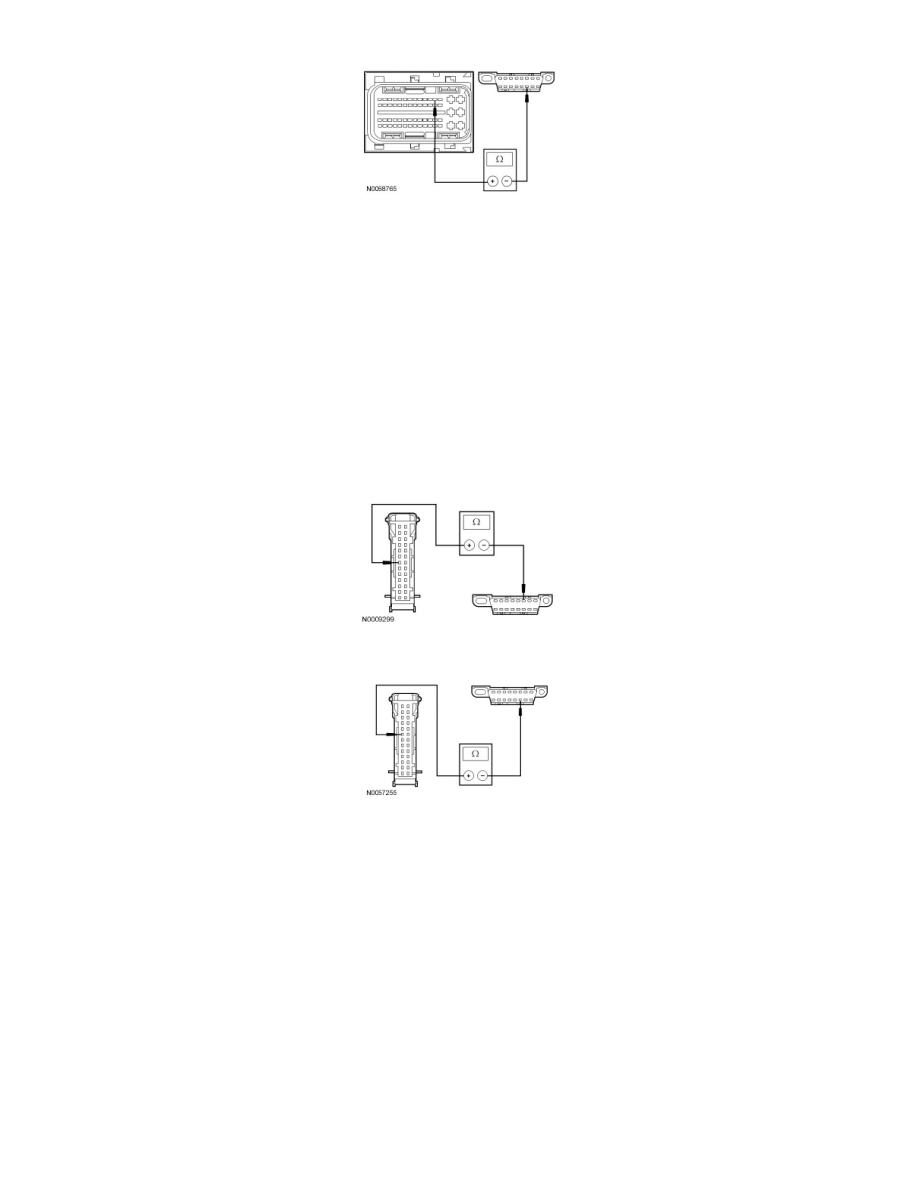
T8 CHECK THE HS-CAN CIRCUITS BETWEEN THE IC AND THE DLC FOR AN OPEN
-
Disconnect: IC C220.
-
Measure the resistance between the IC C220-7, circuit VDB04 (WH/BU), harness side and the DLC C251-6, circuit VDB04 (WH/BU), harness
side.
-
Measure the resistance between the IC C220-6, circuit VDB05 (WH), harness side and the DLC C251-14, circuit VDB05 (WH), harness side.
-
Are the resistances less than 5 ohms?
Yes
GO to T36.
No
REPAIR the circuit in question. CLEAR the DTCs. REPEAT the network test with the scan tool.
-------------------------------------------------
T9 CHECK THE HS-CAN (+) AND HS-CAN (-) CIRCUITS FOR A SHORT TOGETHER
-
Measure the resistance between the DLC C251-6, circuit VDB04 (WH/BU), harness side and the DLC C251-14, circuit VDB05 (WH), harness
side.