
F 250 2WD Super Duty V8-5.4L (2008)
B4
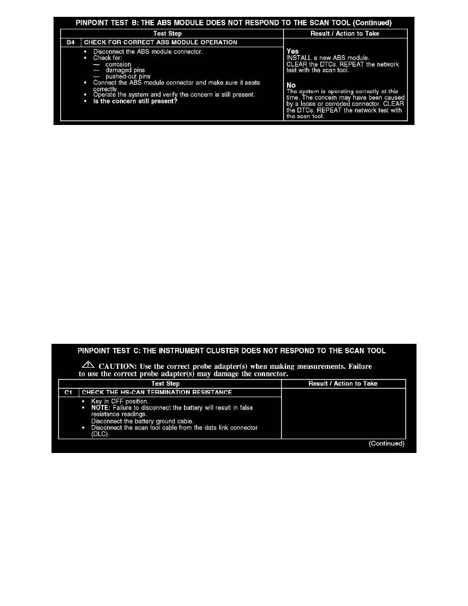
Test C: The Instrument Cluster Does Not Respond To The Scan Tool
PINPOINT TEST C: THE INSTRUMENT CLUSTER DOES NOT RESPOND TO THE SCAN TOOL
Normal Operation
The instrument cluster communicates with the scan tool through the high speed controller area network (HS-CAN) and medium speed controller area
network (MS-CAN). Circuits VDB04 (WH/BU) (HS-CAN +) and VDB05 (WH) (HS-CAN -) provide the HS-CAN network connection to the
instrument cluster and circuits VDB06 (GY/OG) (MS-CAN +) and VDB07 (VT/OG) (MS-CAN -) provide the MS-CAN network connection to the
instrument cluster.
The instrument cluster shares the HS-CAN network with the PCM, ABS module, restraints control module (RCM), transmission control module
(TCM) (diesel engine only, if equipped), supplemental heater control module (diesel engine only, if equipped), variable geometry turbocharger (VGT)
actuator (diesel engine only) and the trailer brake control (TBC) module (if equipped). In addition, the instrument cluster shares the MS-CAN network
with the smart junction box (SJB), driver seat module (DSM) (if equipped), electronic automatic temperature control (EATC) or electronic manual
temperature control (EMTC) module, audio control module (ACM), DVD player (if equipped) and satellite digital audio receiver system (SDARS)
module (if equipped). Voltage for the instrument cluster is provided by circuits CBP36 (BU/BN) and SBP26 (YE/RD). Circuit GD133 (BK) provides
ground.
This pinpoint test is intended to diagnose the following:
-
Fuse
-
Wiring, terminals or connectors
-
Instrument cluster
C1