
F 250 2WD Super Duty V8-5.4L VIN 5 (2006)
14. Disconnect the engine oil pressure (EOP) sensor electrical connector.
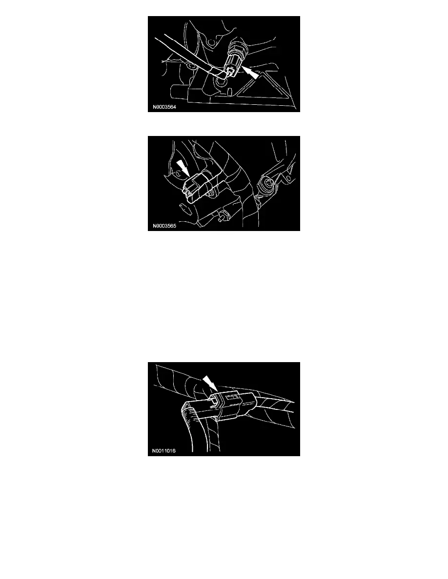
15. Disconnect the LH camshaft position (CMP) sensor electrical connector.
16. Disconnect the LH variable camshaft timing (VCT) solenoid electrical connector.
17. Disconnect the LH radio ignition interference capacitor electrical connector.
18. Disconnect the wiring harness retainers from the LH valve cover studs and position the harness aside.
19. Disconnect the brake booster vacuum hose from the intake manifold vacuum tube.
20. Remove the 10 intake manifold bolts.
21. CAUTION: Do not use metal scrapers, wire brushes, power abrasive discs or other abrasive means to clean the sealing surfaces. These tools
cause scratches and gouges which make leak paths. Use a plastic scraping tool to remove all traces of old sealant.
Remove the 3 bolts, the coolant bypass tube and discard the gaskets.
^
Clean and inspect the sealing surfaces with silicone gasket remover and metal surface prep. Follow the directions on the packaging.
22. Disconnect the charge motion control valve (CMCV) electrical connector.
23. Disconnect the intake manifold vacuum tube from the valve cover stud and the support bracket.
24. Position the intake manifold assembly forward and disconnect the cylinder head temperature (CHT) sensor jumper harness electrical connector.