
F 250 2WD Super Duty V8-5.4L VIN 5 (2006)
4. Install interim 0 degree service adjusters to both sides of the vehicle.
5. Install the upper ball joint pinch bolt and a new nut.
^
Tighten to 80 Nm (59 ft. lbs.).
6. Install the front wheel(s) and check caster and camber readings with the 0 degree service adjusters installed.
7. Calculate the maximum amount of camber and/or caster adjustment required to achieve the optimal settings, as provided in the Alignment
Specifications table, by subtracting the measured values from the optimal target values.
Example: for an E-150,
^
Optimal camber spec target = 0.25 ± 1.0
^
Optimal caster LH spec target - 4.0 ± 2.75.
^
Measured camber = 1.55 (out-of-spec).
^
Measured caster = 3.0 (within spec).
^
Required camber adjustment = 0.25 - 1.55 = -1.3.
^
Preferred caster adjustment = 4.0 - 3.0 = 1.0, however not required.
8. Using the Camber/Caster Service Adjuster table, determine the appropriate replacement service adjuster needed to correct alignment. There is
usually more than one combination of service adjuster and orientation that can be chosen to achieve alignment measurements within specifications.
If a compromise is required, choose the adjuster and orientation which optimizes the camber value and maximizes the caster value.
Example: continuing the above example,
^
Choose an adjuster with a 1-1/2 degree adjustment circle.
^
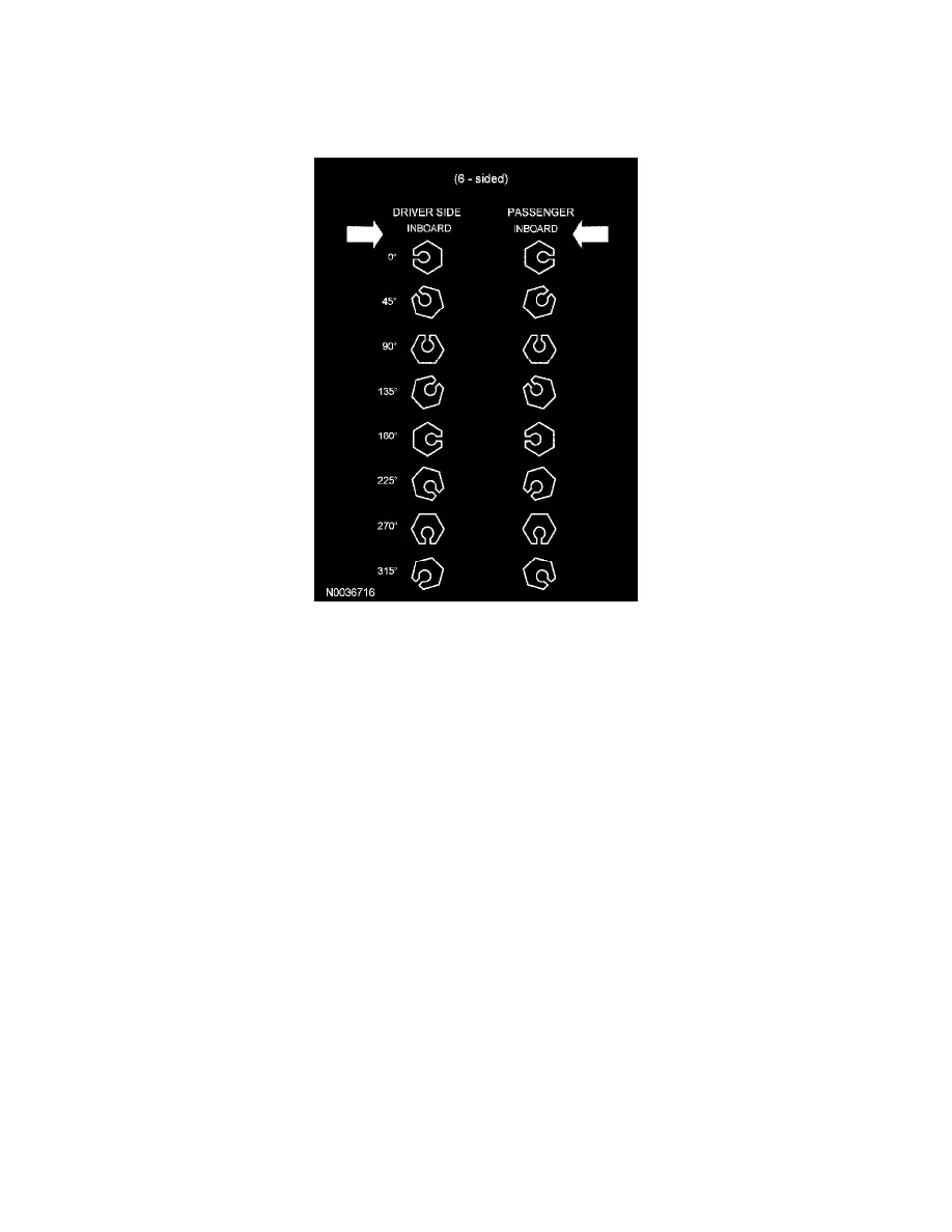
Set the adjuster to the 315 degree position to achieve a -1.05 degree camber and +1.05 degree caster shift setting.
NOTE: When selecting a replacement service adjuster to achieve the desired amount of camber and caster offsets, caution is required to make
sure that all other alignment characteristics (camber split, caster split and individual caster) are maintained to within their specified ranges. When
in doubt which service adjuster to choose, make the selection which achieves measured results closest to the optimal targets in the following order
of priority:
-
Caster split
-
Individual camber
-
Camber split
-
Individual caster
9. Remove the 0 degree service adjusters and install the appropriate replacement service adjusters to the correct rotational orientation specified in the
Camber/Caster Service Adjuster table.