
F 250 2WD Super Duty V8-5.4L VIN 5 (2006)
Trailer Brake Control Module: Initial Inspection and Diagnostic Overview
Principles of Operation
Principles of Operation
The trailer brake control (TBC) module is an integrated electronic control device that is designed to provide variable braking power to the
electric-actuated drum brakes on a towed trailer (1 to 4 axles only). The braking energy that is provided to the trailer is varied with a pulse width
modulated (PWM) signal that switches between 0 volts and battery voltage, the higher the duty cycle the more braking power available.
The TBC module receives information through the controller area network (CAN). These inputs are from the powertrain control module (PCM),
instrument cluster and the anti-lock brake system (ABS) module. The information sent out from the TBC module is through the CAN and is displayed
on the instrument cluster message center.
The TBC module faceplate provides the driver with control buttons to adjust the gain setting UP or DO, which determines the maximum power output
sent to the 7-pin connector. The TBC module faceplate also provides a manual control lever to manually apply the trailer brakes independent of the
vehicle brakes in order to calibrate the gain setting to the specific trailer loading and road conditions. Note that when the manual control is activated,
both the vehicle and the trailer brake lamps illuminate. If there is no trailer connected and the manual control lever is activated, the vehicle brake
lamps still illuminate. The TBC module faceplate displays the gain setting and relative trailer braking power during a braking event. The TBC module
also has an illuminated red or green trailer icon that displays trailer connectivity status to the driver.
The TBC module is operating correctly if these conditions are met. Turn the key to the ON position (no trailer connected). The TBC module LEDs
should not be lit with no pedal or manual input. Verify the slider is not stuck, then set the gain to 10 and slide the manual lever to the left and make
sure the LEDs light up and that the message center says TRAILER DISCONNECTED or CHECK TRAILER. With the vehicle stationary there should
be greater than 10-12 volts supplied to the trailer tow C4099-3 circuit 43 (DB). If these conditions are met the system is considered to be operating
normally.
Inspection and Verification
Inspection and Verification
NOTE: A trailer brake emulator tool is available to verify that the TBC module and vehicle wiring are functioning correctly.
1. Verify the TBC system is correctly installed by checking that the vehicle is equipped with a brake pressure transducer on the master cylinder. If the
brake pressure transducer is not present, then the TBC system has been erroneously installed.
2. Verify the customer concern.
3. NOTE: The TBC does not function with electric-over-hydraulic or surge trailer brake types.
Verify that the trailer brakes are electric-actuated drum type brakes.
4. Verify the stoplamps operate correctly by applying and releasing the brake pedal with the ignition switch in the OFF position and the trailer
disconnected. If the stoplamps operate correctly, proceed to the next step.
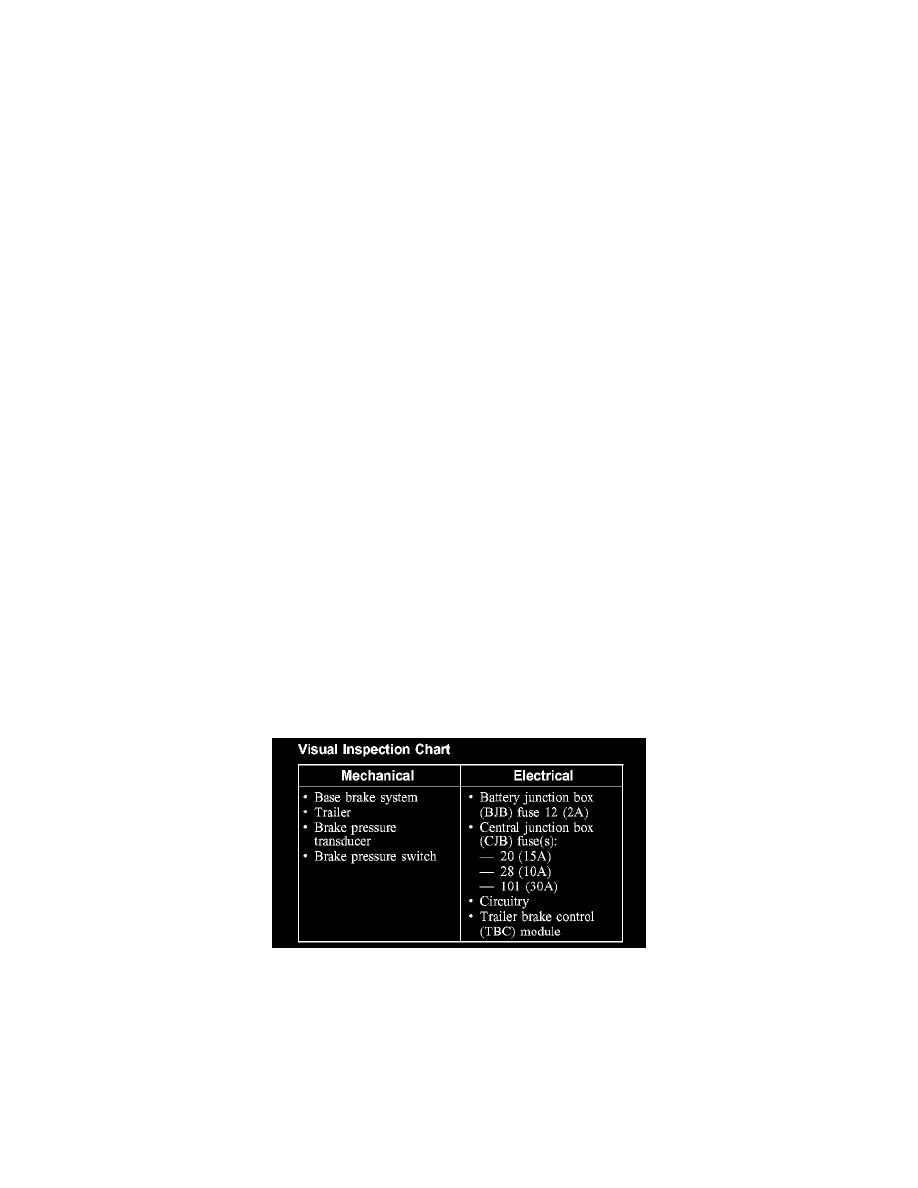
5. Visually inspect for obvious signs of mechanical or electrical damage.
Visual Inspection Chart
6. If the cause is not visually evident, connect the diagnostic tool to the data link connector (DLC) and select the vehicle to be tested from the
diagnostic tool menu. If the diagnostic tool does not communicate with the vehicle:
^
check that the program card is correctly installed.
^
check the connections to the vehicle.
^
check the ignition switch position.
7. If the diagnostic tool still does not communicate with the vehicle, refer to the diagnostic tool operating manual.
8. Carry out the diagnostic tool data link test. If the diagnostic tool responds with:
^
CAN, ISO or UBP circuit fault; all electronic control units no response/not equipped, refer to Information Bus (Multiplex Configurations
Network).