F 250 2WD Super Duty V8-5.4L VIN 5 (2006)

Installation
1. CAUTION: Sometimes, when removing the transmission, the input shaft will remove a considerable amount of lubricant from the transmission
input shaft pilot bearing.
Lubricate the transmission input shaft pilot bearing, as necessary.
^
Use Krytox(R) High-Temperature Grease.
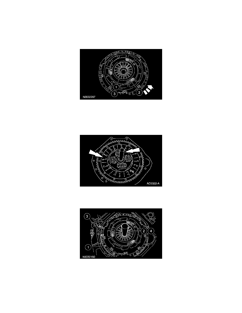
2. CAUTION: When installing the original clutch pressure plate, reset the wear indicator before installing the clutch pressure plate on the flywheel.
Reset the wear indicator.
1
Using a suitable press and adapter, press downward on the fingers until the adjusting ring moves freely.
2
Rotate the adjusting ring counterclockwise to compress the tension springs. Hold the adjusting ring in this position.
3
Release the pressure on the fingers. The adjusting ring will now stay in the reset position.
3. Position the clutch disc on the flywheel and the clutch alignment tool in the pilot bearing to align the clutch disc.
^
The 5.4L/6.8L engines accept a 1-1/4 inch input shaft.
^
The 6.0L engines accept a 1-3/8 inch input shaft with 0.98 inch pilot bearing inner diameter.
4. NOTE: Align the index marks if installing the original clutch pressure plate and flywheel.
Install the clutch pressure plate.
1
Position the clutch pressure plate on the dowels.
^
The diesel engine flywheel has 2 dowels. The gasoline engine flywheel has 3 dowels.
2
Using a suitable clutch alignment tool, align the clutch disc and the pressure plate.
3
Install the clutch pressure plate bolts and tighten in a star pattern sequence.
^
For the 5.4L and 6.8L engines, tighten to 45 Nm (33 ft. lbs.).
