
F 250 2WD Super Duty V8-6.0L DSL Turbo VIN P (2004)
2.
Position and install the plastic TEE over the forward harness take-out with the narrowed end toward the rear of the vehicle. Do not latch the TEE
closed at this time. See Figure 6.
3.
Cut two (2) pieces of 11/16" convolute: one approximately 75 mm (3 inches) long, the other about 37 mm (1.5 inches) long. See Figure 6.
4.
Position the 75 mm (3 inches) section of convolute over the harness takeout from the plastic TEE to the FICM connector. See Figure 6.
5.
Position the 37 mm (1.5 inches) section of convolute between the two (2) harness take-outs. See Figure 6.
6.
Close the TEE around the harness and over the convolute, making sure that all 4 latches are engaged. See Figure 6.
7.
Using the supplied tape, secure the plastic TEE, both sections of convolute and the connector covers. See Figure 6.
8.
Connect the injector connectors.
9.
Position the FICM and connect all three (3) FICM connectors.
10.
Install the FICM retainer bolts. Tighten the bolts to 13 Nm (10 lb-ft).
11.
Proceed to Sensor Connector Replacement in this Attachment V.
FICM HARNESS REPLACEMENT
NOTE:
FICM Harness Replacement must only be performed if copper strands have been exposed caused by chafing of the wires inside the harness.
REMOVAL
1.
CAUTION: While removing the ground stud nut, hold the stud/intake manifold bolt from turning. If the stud/bolt is not held, the intake manifold
bolt may loosen causing the ground wire to twist and eventually break.
Disengage the engine harness from the stud located at the rear of the intake manifold on the driver side of the vehicle, then remove the ground wire
from the stud.
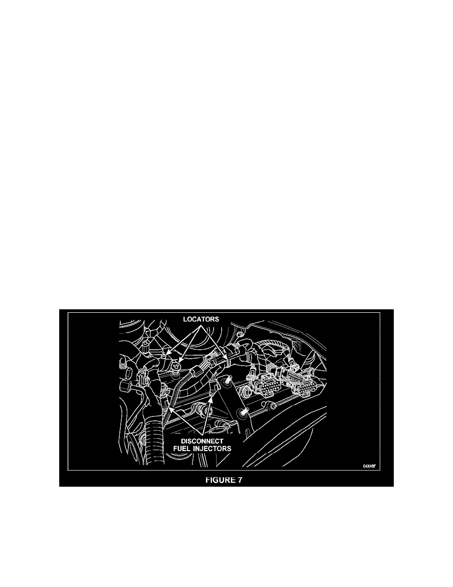
2.
Disconnect the remaining two (2) fuel injectors on the driver side along with three (3) wire harness locators (two [2] located along the fuel injector
manifold assembly and one (1) located underthe turbocharger). See Figure 7.
3.
Remove the charge air cooler (CAC) hot air inlet duct (passenger side of the engine compartment) and the engine oil fill tube from the passenger
side valve cover.