
F 250 4WD HD Pickup V8-460 7.5L VIN G EFI (1997)
^
If the high spot is within 100 mm (4 inches) of the first high spot on the tire, and is still outside of guidelines, replace the tire.
^
If the high spot is not within 100 mm (4 inches) of either original high spot of the tire and rim, then draw an arrow from the second high spot
to the first high spot (in the shortest direction) and rotate the tire on the rim 90 degrees in that direction. This will normally reduce the runout
to an acceptable level.
In the majority of cases, the first 180-degree turn of the tire will either fix the problem or indicate which item to replace.
Runout
DESCRIPTION
Excessive radial and lateral runout of a wheel and tire assembly can cause roughness, vibration, wheel tramp, tire wear, and steering wheel tremor.
Before checking runout, and to avoid false readings caused by temporary flat spots in the tires, check runout only after the vehicle has been driven far
enough to warm the tires.
Measure the extent of the runout with Rotunda Radial Runout Gauge. All measurements are made on the vehicle with the tires inflated to
recommended inflation pressures and with the front wheel bearings adjusted to specifications.
TIRE RUNOUT
Using Rotunda Radial Runout Gauge 007-0056A, measure radial runout of the tire at the center and outside ribs of the tread face. Mark the high
points of radial runout for future reference. On tires, radial runout should not exceed 1.27 mm (0.050 inch).
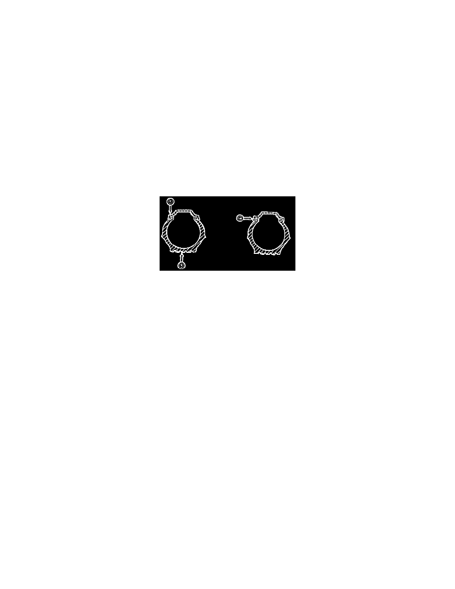
WHEEL RUNOUT
Measure radial and lateral wheel runout at the positions shown in the illustration. Runout should not exceed 1.143 mm (0.045 inch) in either position.
Wheel and Tire Checking
1. Verify the operator's original concern regarding the tires to duplicate the condition.
2. Inspect to determine if the following conditions apply.
^
Incorrect mounting
^
Misalignment
^
Loose wheel bearings
^
Bent wheels
^
Cupping or scalloping of tires from imbalance
^
Possible loose or worn steering connecting rod, drag link and pitman arm
^
Underinflation or mechanical irregularities such as out-of-balance condition of wheel or tire and bent or damaged wheel
^
Loose, damaged or worn front suspension parts
NOTE: Tires that show irregularities and definite roughness must be replaced.
Wheel Damage Inspection
Distorted Wheels
Wheel vibration may be caused by distorted pilot holes or lug holes on the wheel. This does not allow sufficient clamp load between the lug nuts, the
wheel and the rotor/hub. It may also be difficult to remove the distorted wheel from the vehicle or to place the wheel on the vehicle in a different
location. To determine if a wheel has been damaged and should not be reused, refer to the following service procedure for details.
Inspect for Wheel Damage
1. Remove the wheel from the hub. If the wheel is difficult to remove, do not reuse the wheel.
2. Visually inspect the wheel for distortion (turned-up) scallops in the pilot hole. If the pilot hole is distorted, do not reuse the wheel.
3. Inspect the distorted lug holes by placing a lug nut in the lug hole cone seat of the wheel and inspect from the reverse side. If the lug protrudes
through the lug hole, do not reuse the wheel.
4. Inspect the wheel mounting surface for distortion.
a. Lay a straightedge across the mounting surface of the wheel (the surface of the wheel that makes contact with the rear brake drum or front
rotor).
b. The straightedge should contact the outer edge of the mounting surface, lying between the bolt holes and across the center of the pilot hole.
c. The clearance between the straightedge and the pilot hole cannot exceed 0.762 mm (0.030 inch). The straightedge should not contact the pilot