
F 250 4WD Pickup L6-300 4.9L (1982)
contour of the edges of the arm.
3.
With template secure, make a punch mark at the center of the small hole inside the printed circle. Scribe the slot printed/cut-out on the template
and die-grind out the slot at the axle-attaching hole the same size as the slot in the template and de-burr the surface avoiding rounding the edges of
the slot.
4.
Drill a 0.228 inch diameter hole at the punch mark. Use this hole to mount the cam with the 1/4-20 self-tapping screw supplied.
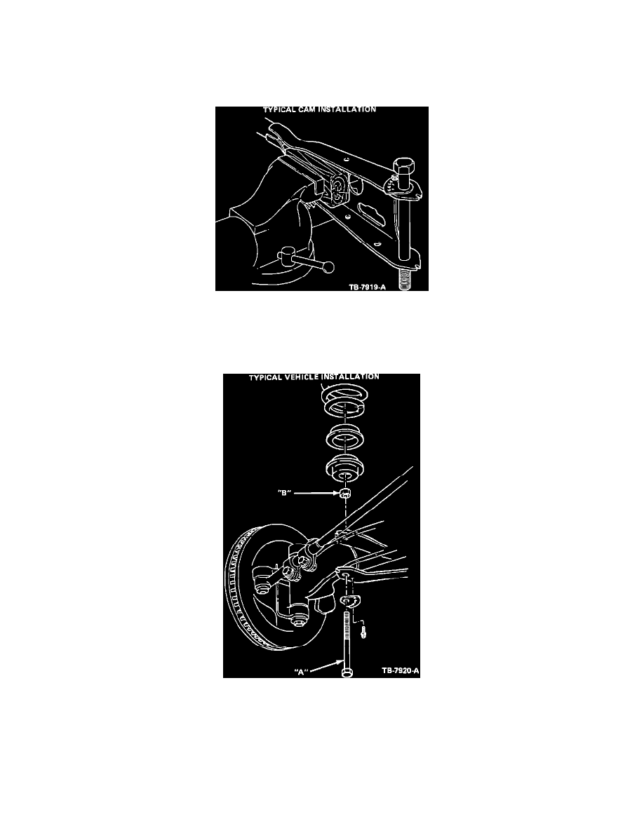
Figure 9
5.
Figure 9 shows a typical cam installation. Each hole in the cam represents a 1/2 degree caster increase. A caster increase of approximately 2
degrees for F-150 4x2 for example will be obtained by mounting the cam with the self-tapping screw in
the No. 2 hole of the cam to the lower flange of the radius arm.
Figure 10
6.
Figure 10 shows a typical F-100/150 4x2 vehicle installation. TORQUE BOLT A AND NUT B TO:
160 to 220 ft.lbs.
Ranger 4x2
270 to 330 ft.lbs.
F Series
7.
Reset front wheel toe to zero after installation is complete.
The following are methods for adjusting caster on vehicles with stamped front axles: