
F 250 4WD Pickup L6-300 4.9L (1982)
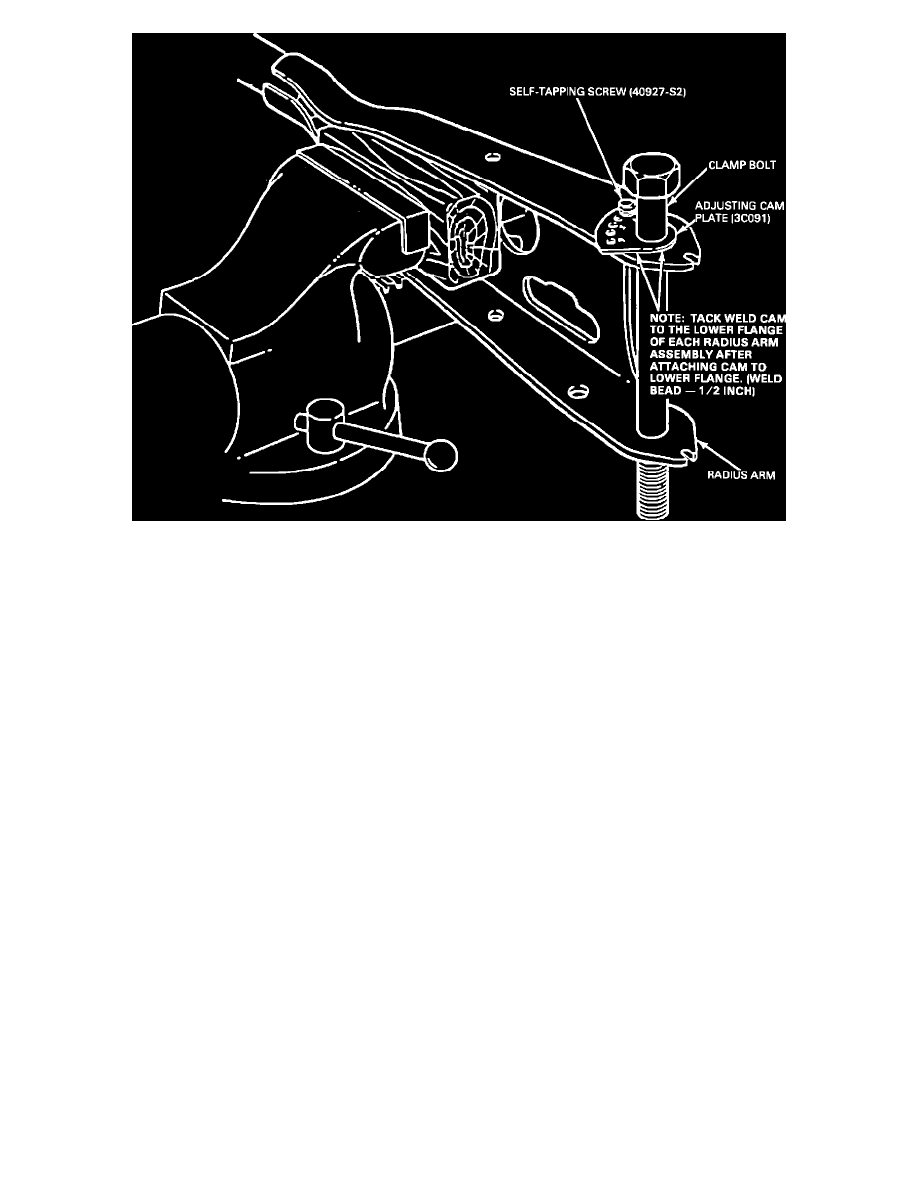
Figure 10 - ATTACHMENT OF ADJUSTING CAM TO RADIUS ARM
4.
Drill a 0.228 inch diameter hole at the punch mark. Use this hole to mount the adjusting cam with the 1/4-20 self-tapping screw supplied. Refer to
Figure 10.
5.
Figure 10 shows a typical cam installation. Each hole in the cam represents a 1/2 degree caster increase. A caster increase of approximately 2
degrees for the E100-350, for example, will be obtained by mounting the cam with the selftapping screw in the No. 2 hole of the cam to the lower
flange of the radius arm.