
F 250 4WD Pickup V8-302 5.0L (1986)
Data Link Connector: Technical Service Bulletins
Diagnostic Connector - Service Bay Diagnostic System
Article No.
93-20-4
09/29/93
^
SERVICE BAY DIAGNOSTIC SYSTEM - REMOVAL OF TACH WIRE FROM VIP/SELF TEST (DLC) CONNECTOR TO AVOID DAMAGE
TO SBDS - THUNDERBIRD/COUGAR WITH 5.0L, BRONCO, F-150-350, ECONOLINE WITH 5.0L/5.8L, AEROSTAR WITH 2.3L, 2.8L,
3.0L
^
WIRING - REMOVAL OF TACH WIRE FROM VIP/SELF TEST (DLC) CONNECTOR TO AVOID DAMAGE TO SBDS -
THUNDERBIRD/COUGAR WITH 5.0L, BRONCO, F-150-350, ECONOLINE WITH 5.0L/5.8L, AEROSTAR WITH 2.3L, 2.8L, 3.0L
^
SBDS DAMAGE-REMOVAL OF TACH SIGNAL WIRE FROM VIP/SELF TEST (DLC) CONNECTOR - THUNDERBIRD/COUGAR WITH
5.0L, BRONCO, F-150-350, ECONOLINE WITH 5.0L/5.8L, AEROSTAR WITH 2.3L, 2.8L, 3.0L
FORD:
1986-88 THUNDERBIRD
LINCOLN-MERCURY:
1986-88 COUGAR
LIGHT TRUCK:
1986 BRONCO, F-150-350 SERIES
1986-87 ECONOLINE
1986-91 AEROSTAR
ISSUE:
The VIP/Self-Test (DLC) connector on certain model year Ford and Lincoln/Mercury vehicles should not be connected to the SBDS without
modification or damage will occur to the SBDS. Refer to the following for service details.
ACTION:
Remove the tach signal wire from the VIP/Self-Test connector before connecting to the SBDS.
The VIP/Self-test (DLC) connector on these vehicles contains a tach wire that generates a voltage spike that damages the MCVI circuit board in the
SBDS. The damage will become evident when SBDS tools that utilize the Data Communications Link (DCL) are used later, on a vehicle equipped with
DCL. Refer to the following detailed service procedure for information.
1.
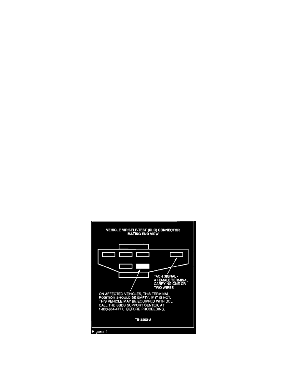
Inspect the vehicle's VIP/Self-Test connector for the presence of a tach signal wire. Refer to Figure 1.
2.
If a tach wire is present, remove it. Using a small flat bladed screwdriver, depress the plastic retaining tab that locks the terminal into the