
F 250 4WD Pickup V8-7.3L DSL Turbo VIN K (1994)
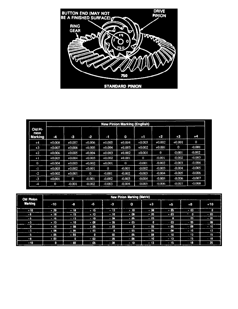
Fig. 8 Ring & Pinion Identification
Pinion to ring gear backlash is controlled by preload shims located between the differential bearing cup and carrier. On the button of each drive
pinion is marked a plus (+), a minus (-) or a zero (0). These markings indicate the position for each gear set. The position is determined by amount
of shims between inner pinion bearing cup and carrier bearing bore. Any pinion depth change is made by changing amount of shims.
Fig. 10 Drive Pinion Adjusting Shim Thickness Chart (Metric)
If the original gear set is being reused, measure the slinger, baffle and each shim separately and add each shim measurement to total original
measurement. Replace old shims with new shims that equal this measurement, if necessary. If a new gear set is being used, notice the plus (+),
minus (-) or zero (0) etchings on both original and new drive pinion and add or subtract shims according to charts to compensate for differences
between old and new pinion.
DEPTH GAUGE INSPECTION