
F 250 4WD Pickup V8-7.3L DSL Turbo VIN K (1994)
NOTE: An alternate method to the previous step, is to invert mainshaft, then secure at output end. Remove gear using a suitable puller.
30. Remove 1st gear caged needle roller bearings from mainshaft.
ASSEMBLE
1. Secure mainshaft in a suitable soft-jawed vise, then place reverse gear caged needle roller bearings on mainshaft.
2. Place reverse gear on mainshaft over caged needle roller bearings, ensuring clutching teeth on reverse gear are facing upward.
NOTE: Before installing original synchronizer ring and synchronizer body, check for excessive wear.
3. Position reverse gear synchronizer ring on taper of reverse gear.
4. Heat 5th/reverse synchronizer body, using a suitable heater to approximately 320° F, ensuring not to heat for more than 15 minutes.
5. Position synchronizer body on mainshaft splines to allow side with deeper hub faces down and short lugs on synchronizer ring to engage gaps in
synchronizer body.
6. Push or lightly tap synchronizer body down until it stops.
7. Install snap ring on mainshaft next to 5th/reverse synchronizer body.
8. Clearance between snap ring and synchronizer body should be 0.0-0.004 inch with zero clearance preferable.
NOTE: Ensure snap ring is free of burrs before checking clearance.
9. Check reverse gear endplay. Endplay must be between 0.006-0.014 inch.
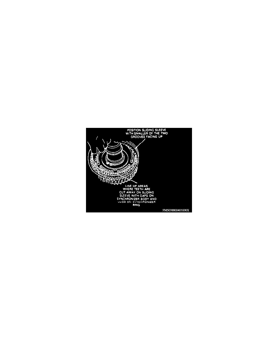
Sleeve Synchronizer Body And Reverse Gear Alignment
10. Position 5th/reverse sliding sleeve with two grooves upward over synchronizer body.
11. Align three cut away positions on sliding sleeve with three gaps on synchronizer body and three lugs on synchronizer ring. Slide sliding sleeve
down until it rests against reverse gear clutching teeth, as shown in the Sleeve Synchronizer Body And Reverse Gear Alignment image.
12. Insert three compression springs with pressure pieces in recesses of synchronizer body.
NOTE: Prior to installing original springs, check springs for serviceability.
13. Push back pressure pieces, using a suitable screwdriver, then push in balls and slide pressure pieces until it rests against ball.
14. Place 5th gear synchronizer ring on synchronizer body, noting that short lugs on synchronizer ring should be located over gaps in 5th/reverse
synchronizer body.
15. Push 5th gear synchronizer ring downward while pulling sliding sleeve into center position.
16. Place both 5th gear caged needle roller bearings on mainshaft then install 5th gear on mainshaft over caged needle roller bearings.
17. Heat inner race of mainshaft rear taper roller bearing, using a suitable gear heater to approximately 32O° F, ensuring not to heat for more than 15
minutes.
18. Place gear on mainshaft, until it seats against stop on mainshaft.
NOTE: If necessary to drive bearing on, do not drive against bearing cone.
19. On all models except 4x4, check 5th gear endplay. Endplay should be 0.006-0.014 inch.