
F 250 4WD Super Duty V10-6.8L VIN S (2001)
Heated Oxygen Sensor: Description and Operation
Heated Oxygen Sensor (HO2S) Monitor
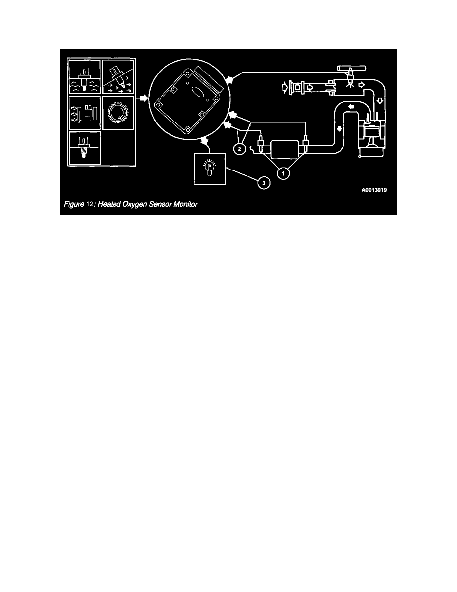
Heated Oxygen Sensor Monitor
The Heated Oxygen Sensor (HO2S) Monitor is an on-board strategy designed to monitor the HO2S sensors for a malfunction or deterioration which can
affect emissions. The fuel control or upstream HO2S is checked for proper output voltage and response rate (the time it takes to switch from lean to rich
or rich to lean). Downstream HO2S used for Catalyst Monitor are also monitored for proper output voltage. The following illustration shows that input is
required from the Engine Coolant Temperature (ECT) or Cylinder Head Temperature (CHT), Intake Air Temperature (IAT), Mass Air Flow (MAF)
and Crankshaft Position (CKP) sensors to activate the HO2S Monitor. The Fuel System Monitor and Misfire Detection Monitor must also have
completed successfully before the HO2S Monitor is enabled.
1. The HO2S sensor senses the oxygen content in the exhaust flow and outputs a voltage between zero and 1.0 volt. Lean of stoichiometric (air/fuel
ratio of approximately 14.7:1), the HO2S will generate a voltage between zero and 0.45 volt. Rich of stoichiometric, the HO2S will generate a
voltage between 0.45 and 1.0 volt. The HO2S Monitor evaluates both the upstream (fuel control) and downstream (Catalyst Monitor) HO2S for
proper function.
2. Once the HO2S Monitor is enabled, the upstream HO2S signal voltage amplitude and response frequency are checked. Excessive voltage is
determined by comparing the HO2S signal voltage to a maximum calibratable threshold voltage. A fixed frequency closed loop fuel control
routine is executed and the upstream HO2S voltage amplitude and output response frequency are observed. A sample of the upstream HO2S signal
is evaluated to determine if the sensor is capable of switching or has a slow response rate. A HO2S heater circuit fault is determined by turning the
heater on and off and looking for a corresponding change in the Output State Monitor (OSM) and by measuring the current going through the
heater circuit. The HO2S Monitor DTCs can be categorized as follows:
The Diagnostic Trouble Code (DTCs) associated with HO2S lack of switching are DTCs P1130, P1131, P1132, P1150, P1151 and P1152.
The DTCs associated with HO2S slow response rate are DTCs P0133 and P0153.
The DTCs associated with HO2S signal circuit malfunction are DTCs P0131, P0136, P0148, P0151 and P0156.
The DTCs associated with a HO2S heater circuit malfunction are DTCs P0135, P0141, P0155 and P0161. The Diagnostic Trouble Code (DTC)
associated with the downstream HO2S not running in on-demand is DTC P1127.
The DTCs associated with swapped HO2S connectors are DTCs P1128 and P1129.
3. The Malfunction Indicator Lamp (MIL) is activated after a fault is detected on two consecutive drive cycles.