
F 250 4WD Super Duty V10-6.8L VIN Y (2006)
3. CAUTION: There is a detent on the TBC module clip that will contact the instrument panel. Do not use excessive force during removal or
damage to the module or instrument panel may result.
CAUTION: Do not push or pry on the plastic face of the module. Do not use tools to remove the TBC module.
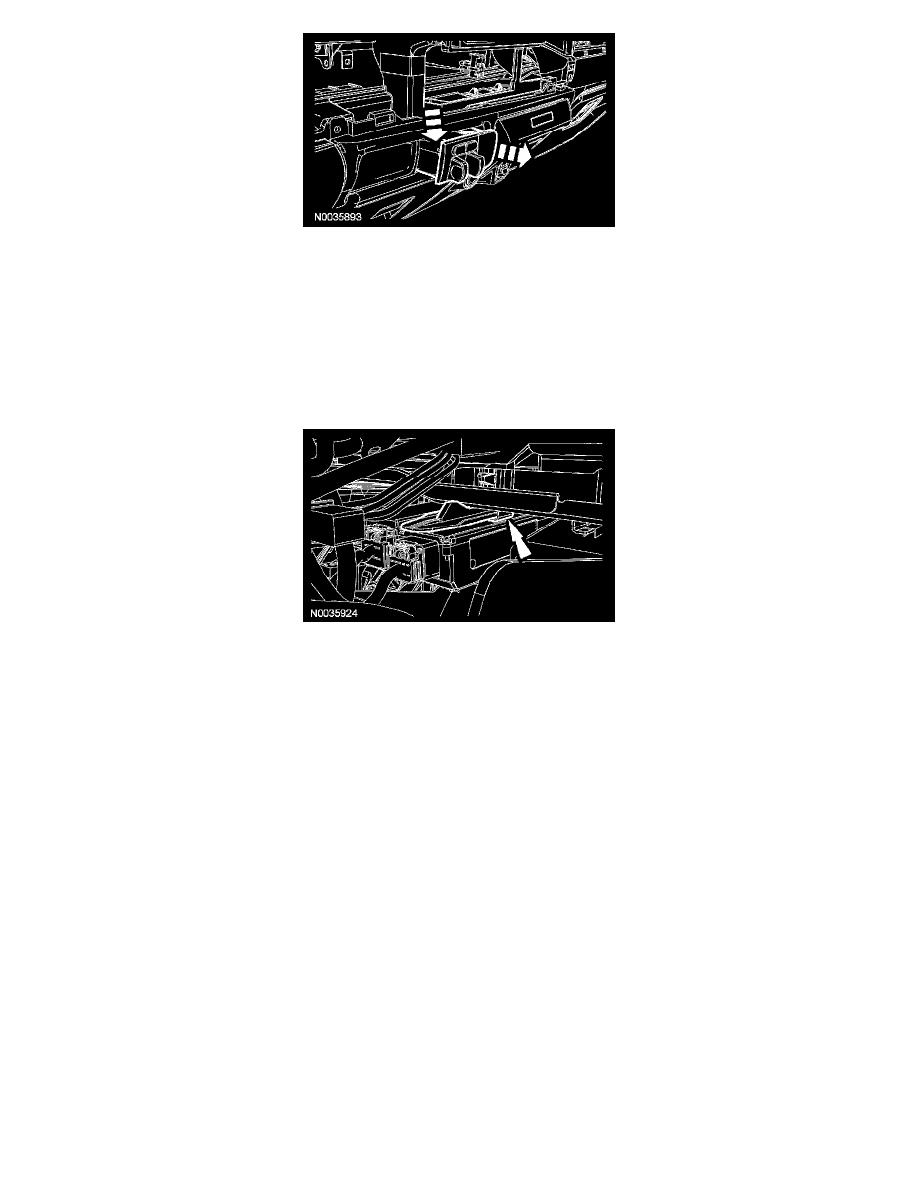
Grasp the TBC module just behind the plastic face and, while carefully pushing down, pull the TBC module out of the instrument panel.
4. Disconnect the 2 TBC module electrical connectors.
Installation
1. Connect the 2 TBC module electrical connectors.
2. NOTE: The locking tab on the top of the TBC module must be aligned with the support bracket inside the instrument panel for correct module
installation and retention.
Align the TBC module locking tab with the support bracket inside the instrument panel and install the module.
3. Install the instrument panel center finish panel. For additional information, refer to Dash Board.