
F 250 4WD Super Duty V10-6.8L VIN Y (2006)
4. Loosen the lower ball joint nut to the end of the lower ball joint stud.
5. CAUTION: Use care not to damage the brake and vacuum lines when striking the spindle.
Separate the wheel knuckle from the axle.
6. Remove the nut from the upper ball joint.
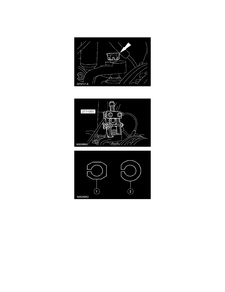
7. Using the special tool, remove the existing LH and RH adjuster sleeves. All vehicles are built by the assembly plant with a non-adjustable
camber/caster sleeve.
1
Service adjusters have a 6-sided flange with the camber/caster adjustment range stamped into the bottom (0 degree, 1/4 degree, 1/2 degree,
3/4 degree or 1 degree).
2
Production adjusters have a round flange with a flattened edge. The amounts of pre-set camber and caster are stamped into the top of the
adjuster.
8. Install interim 0 degree service adjusters to both sides of the vehicle.