
F 250 4WD Super Duty V8-5.4L (2009)
2. Remove the generator.
3. Disconnect the fuel supply spring lock coupling from the fuel rail.
4. Disconnect the upper radiator hose from the thermostat housing.
5. Disconnect the heater coolant hose from the engine coolant crossover manifold assembly.
6. Disconnect the quick connect coupling from the intake manifold and position aside the Evaporative Emission (EVAP) system tube.
7. Disconnect the quick connect couplings and remove the PCV tube.
8. Disconnect the quick connect coupling and position the crank case vent tube aside.
9. Remove the 4 bolts and the Air Cleaner (ACL) outlet pipe-to-Throttle Body (TB) adapter.
10. Disconnect the fuel rail pressure and temperature sensor electrical connector and vacuum connector.
11. Disconnect the 8 fuel injector electrical connectors.
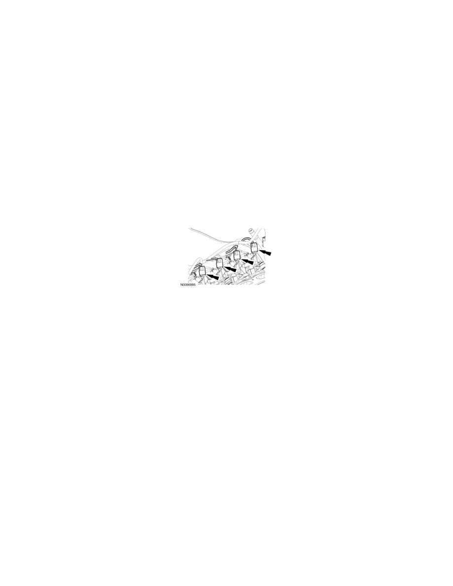
12. NOTE: RH shown, LH similar.
Disconnect the 8 ignition coil electrical connectors.
13. Disconnect the Throttle Position (TP) sensor and Electronic Throttle Control (ETC) electrical connectors.
14. If equipped, disconnect the heated PCV intake fitting electrical connector and connector retainer.
15. Disconnect the LH Variable Camshaft Timing (VCT) solenoid electrical connector.
16. Disconnect the LH radio ignition interference capacitor electrical connector.
17. Disconnect the wiring harness retainers from the LH valve cover studs and position the harness aside.
18. Disconnect the brake booster vacuum hose from the intake manifold vacuum tube.
19. Remove the 10 intake manifold bolts.
20. NOTICE: Do not use metal scrapers, wire brushes, power abrasive discs or other abrasive means to clean the sealing surfaces. These tools
cause scratches and gouges which make leak paths. Use a plastic scraping tool to remove all traces of old sealant.
Remove the 3 bolts, the engine coolant crossover manifold assembly and discard the gaskets.
-
Clean and inspect the sealing surfaces with silicone gasket remover and metal surface prep. Follow the directions on the packaging.
21. Disconnect the intake manifold vacuum tube from the valve cover stud and the support bracket.
22. Disconnect the engine wiring harness retainer from the rear of the intake manifold.
23. NOTICE: Do not use metal scrapers, wire brushes, power abrasive discs or other abrasive means to clean the sealing surfaces. These tools
cause scratches and gouges which make leak paths. Use a plastic scraping tool to remove all traces of old sealant.
Remove the intake manifold and intake manifold vacuum tube as an assembly. Discard the intake manifold gaskets.
-
Clean and inspect the sealing surfaces with metal surface prep and silicone gasket remover. Follow the directions on the packaging.