
F 250 4WD Super Duty V8-5.4L (2009)
Installation
1. NOTICE: If the engine is repaired or replaced because of upper engine failure, typically including valve or piston damage, check the
intake manifold for metal debris. If metal debris is found, install a new intake manifold. Failure to follow these instructions can result in
engine damage.
Using new intake manifold gaskets, position the intake manifold and intake manifold vacuum tube as an assembly.
2. Using new gaskets, position the engine coolant crossover manifold assembly and install the 3 bolts.
-
Tighten to 10 Nm (89 lb-in).
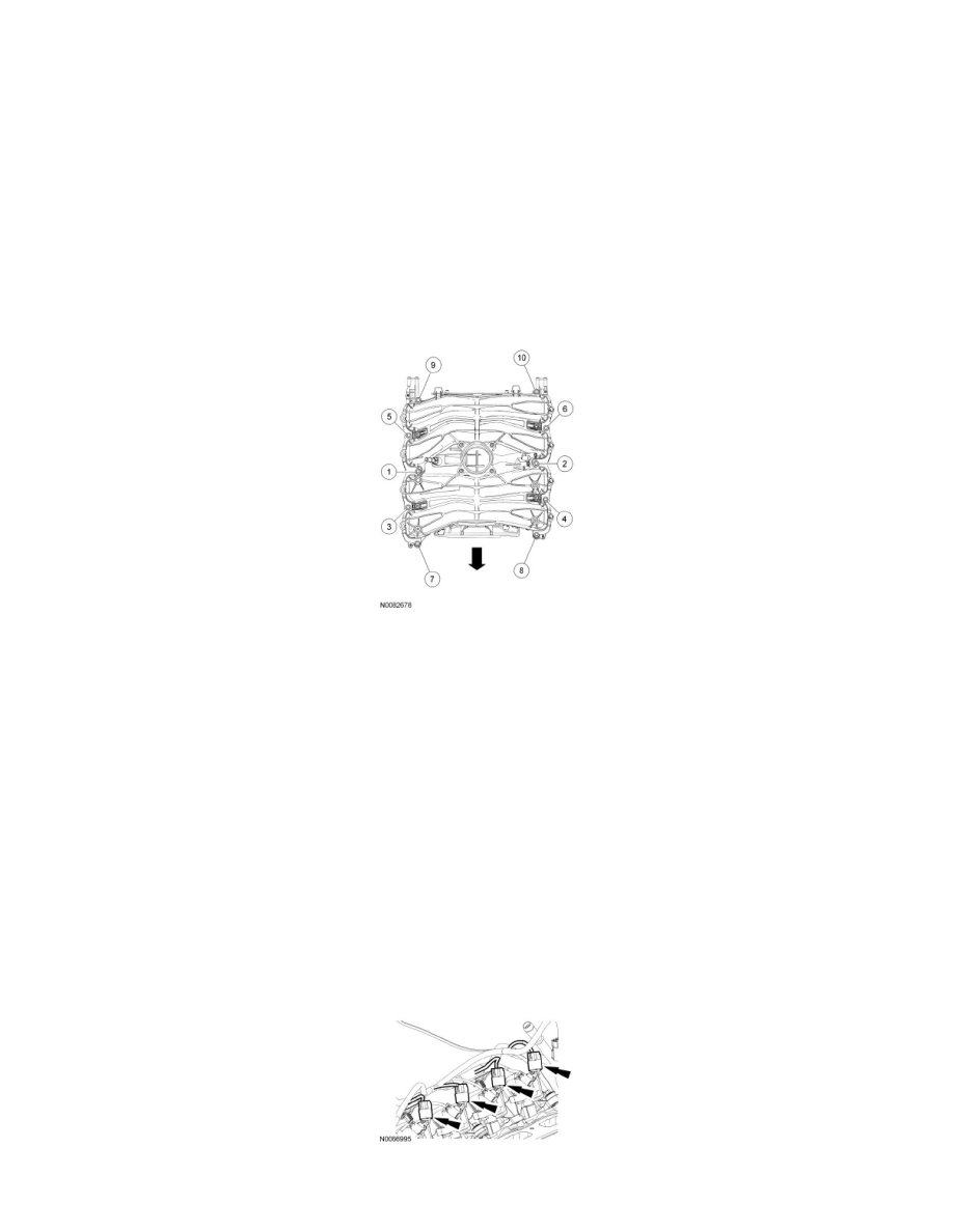
3. Install the 10 intake manifold bolts and tighten in 2 stages in the sequence shown.
-
Stage 1: Tighten to 2 Nm (18 lb-in).
-
Stage 2: Tighten to 10 Nm (89 lb-in).
4. Connect the engine wiring harness retainer to the rear of the intake manifold.
5. Connect the intake manifold vacuum tube to the support bracket and the valve cover stud.
6. Connect the brake booster vacuum hose to the intake manifold vacuum tube.
7. Position the engine wiring harness and connect the wiring harness retainers to the LH valve cover stud bolts.
8. Connect the LH radio ignition interference capacitor electrical connector.
9. Connect the LH VCT solenoid electrical connector.
10. If equipped, connect the heated PCV intake fitting electrical connector and connector retainer.
11. Connect the TP sensor and electronic acceleration control electrical connectors.
12. Connect the 8 fuel injector electrical connectors.
13. NOTE: RH shown, LH similar.
Connect the 8 ignition coil electrical connectors.
14. Connect the fuel rail pressure and temperature sensor electrical connector and vacuum connector.