
F 250 4WD Super Duty V8-5.4L (2009)
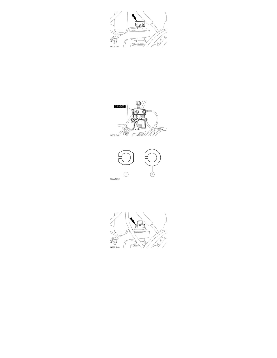
7. Using the Steering Arm Remover, remove the existing LH and RH adjuster sleeves. All vehicles are built by the assembly plant with a
non-adjustable camber/caster sleeve.
1. Service adjusters have a 8-sided flange with the camber/caster adjustment range stamped into the bottom (0 degree, 1/4 degree, 1/2 degree, 3/4
degree or 1 degree).
2. Production adjusters have a round flange with a flattened edge. The amounts of pre-set camber and caster are stamped into the top of the
adjuster.
8. Install interim 0 degree service adjusters to both sides of the vehicle.
9. Install the nut onto the upper ball joint.
-
Tighten to 94 Nm (69 lb-ft).
10. Install the front wheel(s) and check the caster and camber readings with the 0 degree service adjusters installed.
11. Calculate the maximum amount of camber and/or caster adjustment required to achieve the optimal settings, as provided in the Alignment
Specifications table, by subtracting the measured values from the optimal target values.
Example: For a Four-Wheel Drive (4WD) F-350 pickup with Single Rear Wheel (SRW),
-
optimal camber spec target = 0.15 ± 0.75.
-
optimal LH caster spec target = 2.7 ± 1.2.
-
measured camber = 1.2 (out-of-spec).
-
measured LH caster = 2.0 (within spec).
-
required camber adjustment = 0.15 - 1.2 = -1.05.
-
preferred caster adjustment = 2.7 - 2.0 = +0.7, however not required.