
F 250 4WD Super Duty V8-5.4L SOHC VIN L (1999)
10.
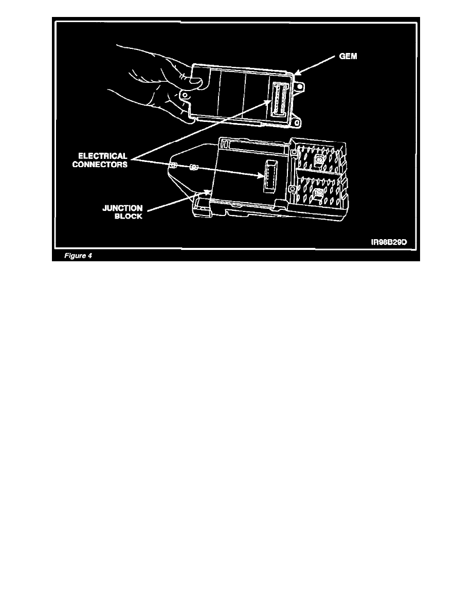
Attach new GEM to junction block. Make sure electrical connector is fully seated. See Figure 4.
11.
Install GEM-to-junction block retaining screws. Tighten screws to 2-3 Nm (18-26 lb-in).
12.
Position junction block assembly in vehicle.
13.
Connect two (2) GEM electrical connectors.
14.
Connect two (2) junction block electrical connectors. Tighten retaining screws to 5-6 Nm (44-53 lb-in).
15.
Install four (4) junction block assembly retaining bolts/nuts. Tighten retaining screws to 5-6 Nm (44-53 lb-in).
16.
Install steering column lower opening panel (knee bolster).
17.
Connect battery negative cable.
18.
On vehicles equipped with manual transmission, proceed as follows:
Reconfigure GEM for manual transmission as follows:
-
Obtain Ford Service Function (FSF) Program card with software level of 4.0 or higher.
-
Insert FSF Program Card into NGS.
-
Connect NGS into the DLC.
-
Turn ignition switch to Run position (engine off).
-
Scroll highlighted bar to "SERVICE BAY FUNCTIONS," then press trigger button.
-
Scroll highlighted bar to "GEM - GENERIC ELECTRONIC MODULE," then press trigger button.
-
Scroll highlighted bar to "MANUFACTURE OPTIONS," then press trigger button.
^
If the NGS displays: "-COMMUNICATION LINK ESTABLISHED - YOU MUST MAKE SELECTION FOR THE FOLLOWING FIELD:
VEHICLE," press trigger button.