
F 250 4WD Super Duty V8-6.4L DSL Turbo (2008)
3. NOTE: Do not turn the crankshaft during this step.
Install and tighten to specifications, then remove the connecting rod bearing cap.
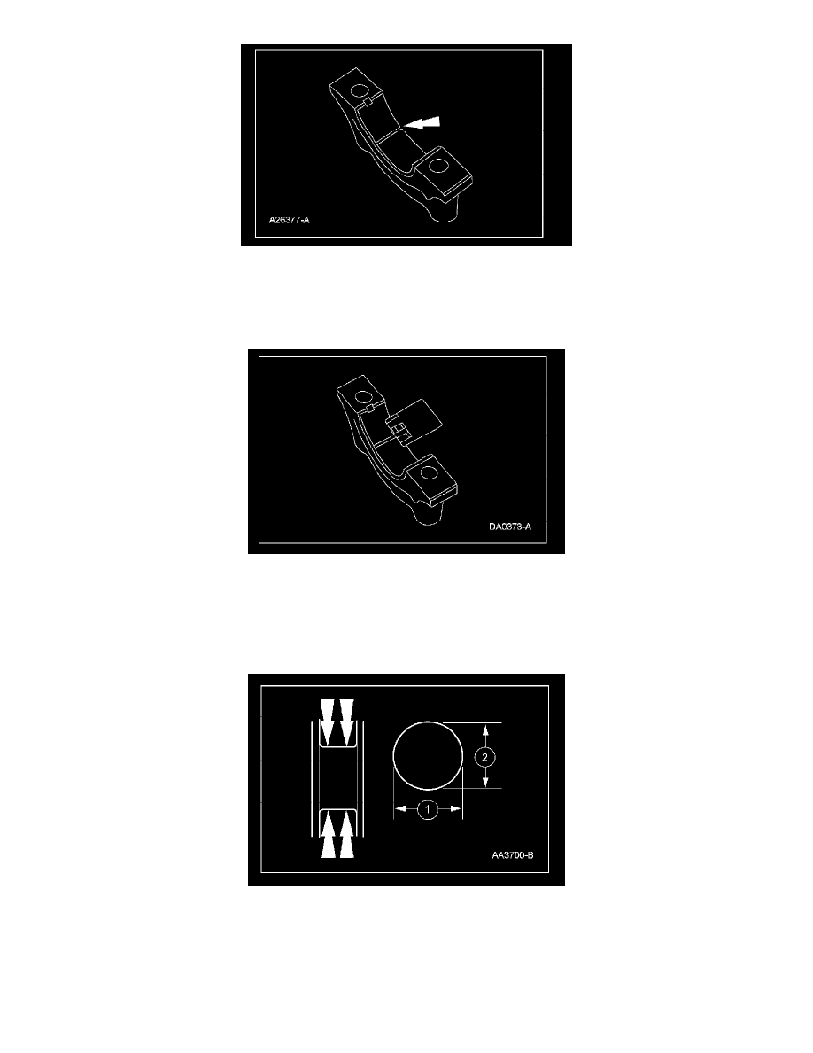
4. Measure the Plastigage(R) to get the connecting rod bearing journal clearance. The Plastigage(R) should be smooth and flat. A changing width
indicates a tapered or damaged connecting rod or connecting rod bearing.
Connecting Rod Bearing Journal Taper and Out-of-Round
NOTE: Refer to the appropriate information for the specification.
1. Measure the crankshaft connecting rod journal diameters in 2 directions perpendicular to one another at each end of the connecting rod journal.
The difference in the measurements from one end to the other is the taper. Verify measurement is within the wear limit.