
F 250 4WD Super Duty V8-6.4L DSL Turbo (2008)
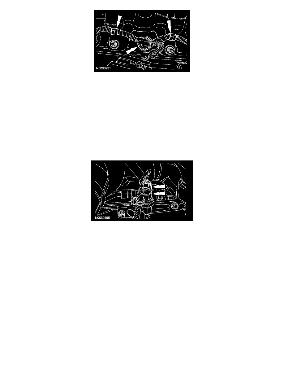
15. NOTE: Only one glow plug connector shown.
Install the glow plug harness and connect the retainers.
-
Make sure the seals are securely seated in the valve cover.
16. NOTE: Install a new O-ring seal prior to installing the oil level indicator and tube.
Install the oil level indicator and tube and the bolt.
-
Tighten to 13 Nm (115 lb-in).
17. Install the retaining nut for the oil level indicator and tube bracket.
-
Tighten to 31 Nm (23 lb-ft).
18. Position back the engine wiring harness. Connect the turbocharger actuator electrical connector and retainer.
19. Connect the glow plug harness electrical connector and pushpin retainers.
20. Connect the EP sensor assembly electrical connector and retaining clip.
RH glow plug sleeve
21. CAUTION: To prevent engine damage, do not use air-powered tools when installing the valve cover.
NOTE: Alternately tighten the bolts to tighten evenly. Install new press-in-place gaskets.
Install the valve covers, bolts and stud bolts.
-
Tighten to 9 Nm (80 lb-in).
22. Position the oil drain back tube and install the nut.
-
Tighten to 13 Nm (115 lb-in).