
F 250 4WD Super Duty V8-7.3L DSL Turbo VIN F (2001)
Bearings from the differential case at this time.
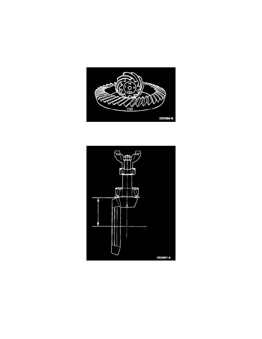
Pinion Ring Gear Variation Number
NOTE: If so equipped, install a new pinion shaft oil slinger if bent or mutilated.
NOTE: The differential ring gear and pinion is only available in a matched set. Matching numbers etched on both the differential ring gear and pinion
are for verification. If installing a new differential ring gear and pinion, verify these numbers match before proceeding with assembly. The end of the
pinion with the etched figures is the "button" end.
NOTE: Use the gear contact pattern method to verify the final pinion position is valid.
1. Shim the pinion as follows:
^
Etched on the button end of each pinion is a zero (0), or a plus (+) or minus (-) with a number. This number indicates the best running position
for each particular differential ring gear. Shimming behind the inner pinion bearing controls this dimension.
2. Measure between the centerline of the differential ring gear to the back face of the drive pinion. The distance must be 147.6 mm (5.812 inch).
3. If reusing the old differential ring gear and pinion, measure and record the old drive pinion position shim thickness and select a new shim of the
same dimension.
^
To change the pinion adjustment, shims are available in the thickness of 0.69 - 1.68 mm (0.027 - 0.066 inch). Measure each shim separately
with a micrometer.
4. If installing a new differential ring gear and pinion, notice the (+) or (-) etching on both the old and new pinion, and adjust the new shim thickness
to compensate for the difference of these two figures. If so equipped, include the oil slinger thickness in the total measurement to correctly set
pinion depth.
^
For example, a pinion etched with m+8 (+3) requires 0.08 mm (0.003 inch) less shimming than a pinion etched "0". This means to increase the
mounting distance by the amount etched in the pinion, subtract 0.08 mm (0.003 inch) from the drive pinion position shim selected for
installation. A pinion etched m-8 (3), requires 0.08 mm (0.003 inch) more shimming than a pinion etched "0". In this instance, add 0.08 mm
(0.003 inch) to the drive pinion position shim selected for installation to decrease the pinion mounting distance by the amount etched in the