
F 350 2WD Pickup V8-351 5.8L (1983)
Crankshaft Position Sensor: Description and Operation
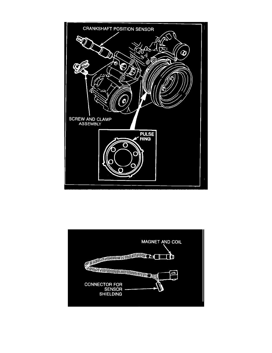
Crankshaft Position Sensor Installation
The crankshaft position (CP) sensor provides electrical input to the ECA for engine speed and control of ignition timing. The sensor sends electrical
signals based on the movement of a crankshaft pulse ring.
The CP sensor mounts directly in front of the cylinder block and is a aligned with the crankshaft pulse ring (the ring is positioned 10° BTDC on the
crankshaft) Fig. 19. The sensor identifies the actual position of the crankshaft (pistons).
CP Sensor
The sensor, Fig. 20, operates much like the distributor pick-up coil and armature which turn On and Off the primary circuit. The tip contains a permanent
magnet and wire coil. As the crankshaft turns, the individual pulse ring lobes approach and finally align with the sensor tip (there are 4 lobes spaced 90°
apart). The metal lobe cuts the magnetic field. This interruption creates an electrical output signal from the CP sensor to the ECA.
The ECA interprets the pulses as crankshaft positions to control spark timing. It also interprets the engine speed (RPM) along with the crankshaft