
F 350 2WD Pickup V8-460 7.5L VIN G EFI (1997)
Piston: Service and Repair
Removal and Installation
REMOVAL
1. Drain the crankcase. Drain the cooling system.
2. Remove the lower intake manifold, cylinder heads, oil pan and oil pump.
3. Remove any ridge or deposits from upper end of cylinder bores as follows:
a. Turn the crankshaft until the piston to be removed is at bottom of its travel.
b. Place a cloth on top of the piston to collect cuttings.
c. Remove any ridge or deposits from the upper end of the cylinder bore. Remove the cylinder ridge with a ridge cutter. Follow instructions
furnished by tool manufacturer. Never cut into ring travel area in excess of 0.79 mm (1/32 inch) when removing ridges.
d. Repeat the procedure at the remaining cylinders.
4. Make sure all connecting rod bearing caps are marked so they can be installed in their original positions.
5. Turn the crankshaft until the connecting rod being removed is down.
6. Remove the connecting rod nuts and connecting rod bearing cap.
7. Push the connecting rod and piston out through the top of the cylinder with the handle end of a hammer or a suitable piston hammer.
CAUTION: Avoid damage to the crankshaft journal and cylinder wall when removing the piston and connecting rod.
8. Remove the connecting rod bearings from the connecting rod and connecting rod bearing cap.
9. Install the connecting rod bearing cap on the connecting rod from which it was removed.
INSTALLATION
1. If new partial piston ring sets are to be installed, remove the cylinder wall glaze. Clean cylinder bores with soap and water after honing or
Reglazing. Dry and oil immediately after cleaning.
2. Oil the partial piston ring sets, pistons and cylinder walls with recommended quality engine oil. Be sure to install pistons into cylinders from which
they were removed or to which they were fitted. Connecting rod and connecting rod bearing caps are numbered from 1 to 4 in the right bank and 5
to 8 in the left bank, beginning at the front of engine. Numbers on the connecting rod and connecting rod bearing cap must be on the same side
when installed in the cylinder bore. If a connecting rod is ever transposed from one cylinder block or cylinder to another, new connecting rod
bearings should be fitted and the connecting rod should be numbered to correspond with the new cylinder number.
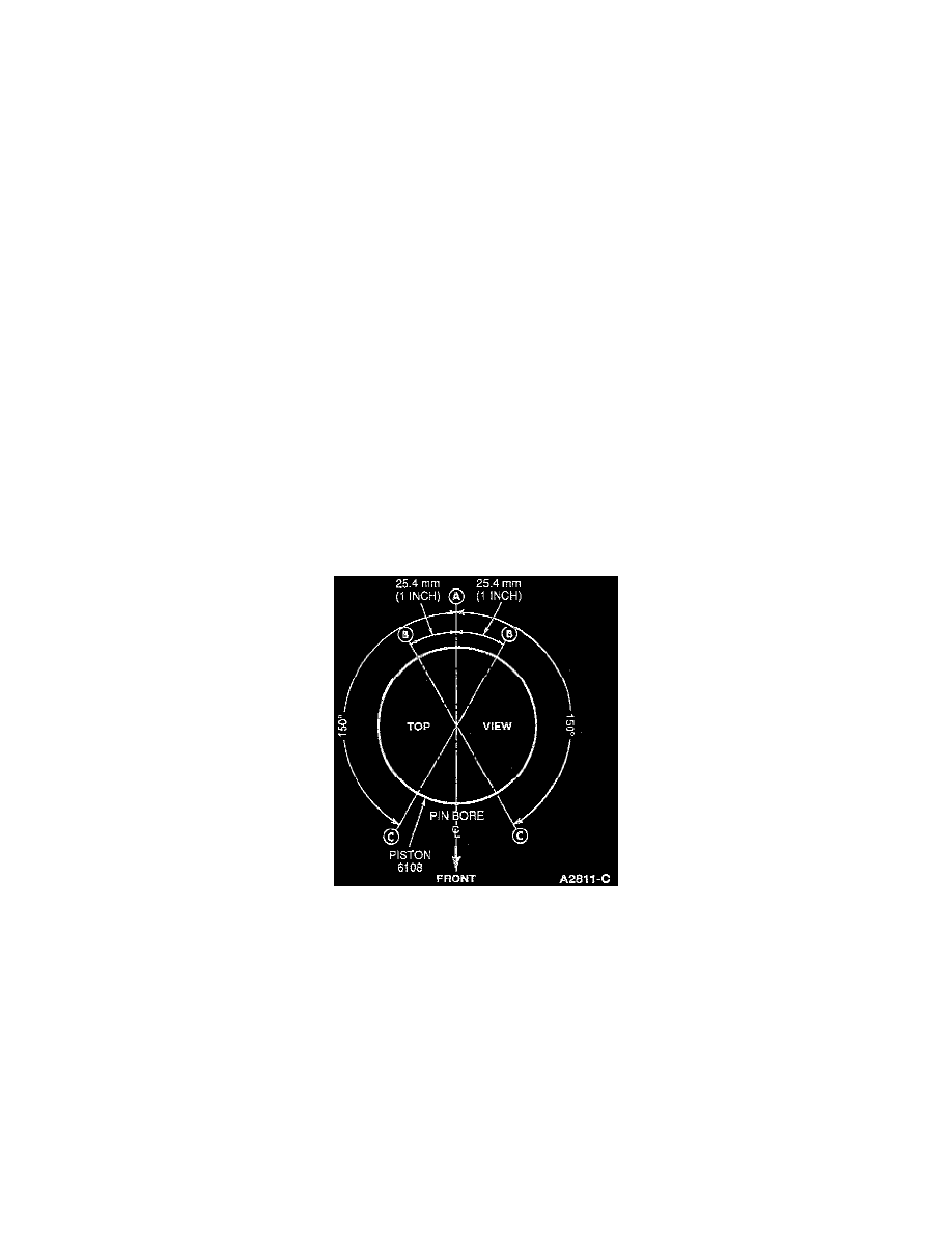
3. Make sure piston ring gaps (oil ring spacer A, oil ring segments B. and compression rings C) are properly spaced around circumference of piston.
NOTE: Refer to the illustration.
4. Turn the crankshaft until the connecting rod journal reaches the bottom of its stroke.