
F 350 2WD Pickup V8-460 7.5L VIN G EFI (1997)
Valve Clearance: Adjustments
The valve arrangement on the left bank is E-l-E-I-E-I-E-I and on the right bank is l-E-I-E-I-E-I-E.
A 1.52-mm (0.060-inch) shorter push rod or a 1.52-mm (0.060-inch) longer push rod is available for service to provide a means of compensating for
dimensional changes in the valve mechanism.
Valve stem-to-valve rocker arm clearance should be within specifications. With the hydraulic valve tappet completely collapsed, repeated valve
reconditioning operations (valve or valve seat refacing) will decrease the clearance to the point that if not compensated for, the hydraulic valve tappet
will cease to function and the intake valve or exhaust valve will be held open.
The use of a positive stop rocker arm seat bolt eliminates the need for valve clearance adjustment. However, to obtain accurate valve clearance
measurements, it is important that all components be serviceable and installed to specification.
To determine whether a shorter or a longer push rod is necessary, perform the following check:
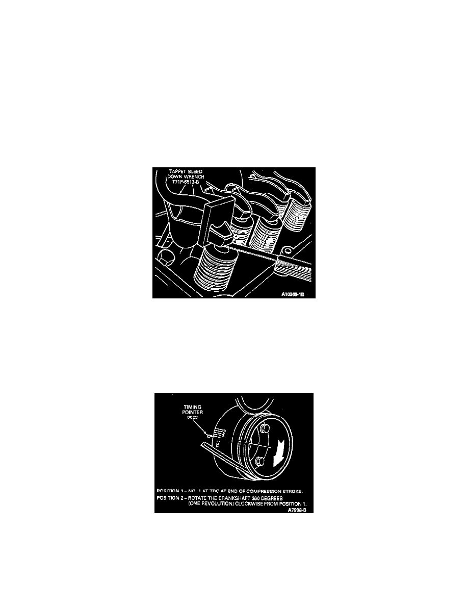
1. Install an auxiliary starter switch. Crank the engine with the key off until the No.1 piston is on TDC after the compression stroke.
2. With the crankshaft in the positions designated in the following Steps 3, 4 and 5, position the hydraulic tappet compressor Tappet Bleed Down
Wrench T71P-6513-B on the rocker arm. Slowly apply pressure to bleed cowl the hydraulic valve tappet until the plunger-is completely bottomed.
Hold the valve tappet in this position and check the available clearance between the rocker arm and the valve stem tip with a feeler gauge. If the
clearance is less than specifications, install a shorter push rod. If the clearance is greater than specifications, install a longer push rod.
3. With the No. 1 piston at TDC at the end of the compression stroke (Position No. 1), check clearances on the following valves:
^
No. 1 Intake No. 1 Exhaust
^
No. 31ntake No. 4 Exhaust
^
No. 7 Intake No. 5 Exhaust
^
No. 8 Intake No. 7 Exhaust
4. After checking the clearance on these intake valves and exhaust valves, rotate the crankshaft 360 degrees to Position No. 2, then check the
following valves:
^
No. 2 Intake No. 2 Exhaust
^
No. 4 Intake No. 3 Exhaust
^
No. 5 Intake No. 6 Exhaust
^
No. 6 Intake No. 7 Exhaust